Download
1 / 26
260 likes | 337 Views
SIPART PS2 is currently the most widely used positioner for linear and part-turn actuators in a wide range of process industries. This is not without reason. The proven all-round design has a particularly flexible stroke range, intelligent diagnostics, and communicates either via HART, PROFIBUS PA or Foundation Fieldbus. What has been proven so often is certainly the correct choice.<br>For More Information visit on:- www.seeautomation.com<br>Our Mail I.D:- sales@seeautomation.com<br>Contact Us:- 91-11-22012324 , 8144883403<br>

E N D
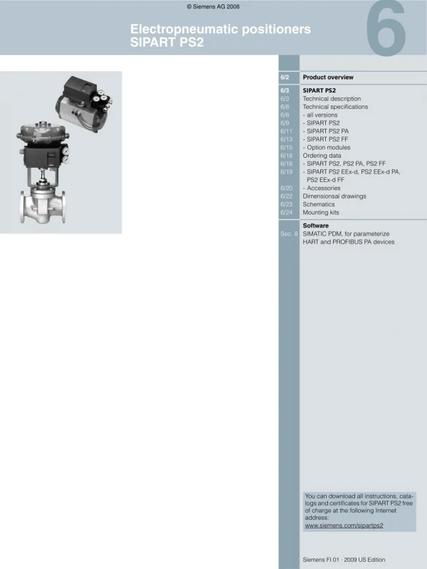
© Siemens AG 2008 Electropneumatic positioners SIPART PS2 6/2 Product overview 6/3 6/3 6/8 6/8 6/9 6/11 6/13 6/15 6/18 6/18 6/19 SIPART PS2 Technical description Technical specifications - all versions - SIPART PS2 - SIPART PS2 PA - SIPART PS2 FF - Option modules Ordering data - SIPART PS2, PS2 PA, PS2 FF - SIPART PS2 EEx-d, PS2 EEx-d PA, PS2 EEx-d FF - Accessories Dimensionsal drawings Schematics Mounting kits 6/20 6/22 6/23 6/24 Software Sec. 8 SIMATIC PDM, for parameterize HART and PROFIBUS PA devices You can download all instructions, cata- logs and certificates for SIPART PS2 free of charge at the following Internet address: www.siemens.com/sipartps2 Siemens FI 01 · 2009 US Edition
© Siemens AG 2008 Electropneumatic positioners Product overview ■ Overview Application Device description Catalog page Software for parameterization Electropneumatic positioners SIPART PS2 Position control Pneumatic linear or part- turn actuators, also for intrinsically-safe opera- tion 6/3 SIMATIC PDM SIPART PS2 Universal device for positioning pneumatic actuators • Connection: 4 to 20 mA • HART, PROFIBUS PA or Foundation Fieldbus • Local manual operation • Binary inputs and outputs • Diagnosis functions • Blocking function • Automatic startup As above, but in flame- proof casing for explo- sion-proof application 6/3 SIMATIC PDM SIPART PS2 As above, but in flameproof aluminium casing 6 6/2 Siemens FI 01 · 2009 US Edition
© Siemens AG 2008 Electropneumatic positioners SIPART PS2 Technical description ■ Overview ■ Benefits SIPART PS2 positioners offer decisive advantages: • Simple installation and automatic commissioning (self-adjust- ment of zero and span) • Simple operation with - Local operation and configuration of the device using three input keys and a user-friendly two-line LCD - Programming through SIMATIC PDM • Very high-quality control thanks to an online adaptation proce- dure • Negligible air consumption in stationary operation • "Tight shut-off" function (ensures maximum positioning pres- sure on the valve seat) • Numerous functions can be activated by simple configuring (e.g. characteristics and limits) • Extensive diagnosis functions for valve and actuator • Only one device version for linear and part-turn actuators • Few moving parts, hence insensitive to vibrations • External non-contacting position sensor as option for extreme ambient conditions • "Intelligent solenoid valve": Partial Stroke Test and solenoid valve function in a single device • Partial Stroke Test e.g. for safety valves • SIL (Safety Integrity Level) 2 • Can also be operated with natural gas SIPART PS2 electropneumatic positioner 6 ■ Application The SIPART PS2 positioner is used, for example, in the following industries: • Chemical/petrochemical • Power stations • Paper and glass • Water, waste water • Food and pharmaceuticals • Offshore plants The SIPART PS2 positioner is available: • For single-action actuators: in plastic, stainless steel or alumi- num casings, as well as flameproof aluminium casing (EEx d) • For double-action actuators: in plastic and stainless steel cas- ing, as well as flameproof aluminum casing (EEx d) • For non-hazardous applications • For hazardous applications in the designs - as intrinsically-safe device (EEx ia/ib) or - in flameproof aluminum casing (EEx d) or - in EEx n design (non sparking) and in the versions: • 0/4 to 20 mA control communication without/with communica- tion through HART signal • With PROFIBUS PA communication interface • With FOUNDATION Fieldbus (FF) communications interface. SIPART PS2 EEx d electropneumatic positioner in flameproof casing SIPART PS2 in stainless steel casing The SIPART PS2 electropneumatic positioner is used to control the final control element of pneumatic linear or part-turn actua- tors. The electropneumatic positioner moves the actuator to a valve position corresponding to the setpoint. Additional function inputs can be used to block the valve or to set a safety position. A binary input is present as standard in the basic device for this purpose. Explosion-proof versions The basic version of the device is available in an intrinsically- safe design with degree of protection EEx ia/ib or in a design with approval for zone 2/zone 22 (dust). Operation in zone 1 is permitted when enclosed in the flame- proof casing version SIPART PS2 EEx d. (see "Technical Data"). It is then permissible to use all option modules (except external actuator travel detection systems, SIA module, limit value con- tact module and NCS). 6/3 Siemens FI 01 · 2009 US Edition
© Siemens AG 2008 Electropneumatic positioners SIPART PS2 Technical description conditions at the fitting exceed the specified values for the posi- tioner (e.g. strong vibrations). The following can be used for measuring the travel or angle: • NCS sensor • External position detection system C73451-A430-D78 • A commercially available potentiometer (10 kΩ resistance) (e.g. for higher application temperatures or customer-specific applications) The use of linear potentiometers is recommended for very small ac- tuators with a short valve travel since, on the one hand, the space required by the linear potentiometer is very small and, on the other, the transmission characteristic is optimum for a small travel. Stainless steel casing for extreme ambient conditions The SIPART PS2 is available in a stainless steel casing (without window in the lid) for use in particularly aggressive environments (e.g. offshore operation, chlorine plants etc.). The device func- tions are the same as those of the basic versions. ■ Design The SIPART PS2 positioner is a digital field device with a highly- integrated microcontroller. The positioner consists of the following components: • Casing and cover • PCB with corresponding electronics with or without communi- cation through HART or with electronics for communication in accordance with - PROFIBUS PA specification, IEC 61158-2; bus-supplied de- vice, or - FOUNDATION Fieldbus (FF) specification, IEC 61158-2, bus-supplied device • Actuator travel detection system • Terminal housing with screw terminals • Pneumatic valve manifold with piezoelectric valve precontrol. The valve manifold is located in the housing, the pneumatic con- nections for the inlet air and the positioning pressure on the right- hand side. A pressure gauge block and/or a safety solenoid valve can be connected there as options. The SIPART PS2 posi- tioner is fitted to the linear or part-turn actuator using an appro- priate mounting assembly. The circuit board container in the casing provides slots for separately ordered boards with the following functions: 6 Separate connection of actuator travel detection system and controller unit Iy module: • Position feedback as a two-wire signal 4 to 20 mA. Non-contacting position sensor (NCS) Alarm module (3 outputs, 1 input): • Signaling of two limits of the travel or angle by binary signals. The two limits can be set independently as maximum or mini- mum values. • Output of an alarm if the setpoint position of the final control element is not reached in automatic mode or if a device/fitting fault occurs. • Second binary input for alarm signals of for triggering safety reactions e. g. for blocking function or safety position. Contact and non-contacting positioning sensor (NCS) for part-turn actu- ator (left) and for linear actuator 14 mm (0.55 inch) (right) Limit signaling through slot-type initiators (SIA module) Two limits can be signaled redundantly as NAMUR signals (EN 60947-5-6) by slot-type initiators. The module also contains an alarm output (see Alarm module). Limit value signal via mechanical contacts (Limit value con- tact module) Two limits can be signaled redundantly by switching contacts. A fault message output is also integrated in the module (see alarm module). Valid for all modules described above: All signals are electrically isolated from one another and from the basic unit. The outputs indicate self-signaling faults. The mod- ules are easy to retrofit. Separate mounting of actuator travel detection system and controller unit The actuator travel detection system and controller unit can be connected separately for all casing versions of the SIPART PS2 (except flameproof design). Measurement of the travel or angle is carried out directly on the actuator. The controller unit can then be fitted a certain distance away, e.g. on a mounting pipe or sim- ilar, and is connected to the travel detection system by an elec- tric cable and to the actuator by one or two pneumatic lines. Such a split design is frequently advantageous if the ambient NCS for travels >14 mm (0.55 inch) 6/4 Siemens FI 01 · 2009 US Edition
© Siemens AG 2008 Electropneumatic positioners SIPART PS2 Technical description The NCS sensor consists of a non-contacting position sensor. All coupling elements are omitted such as coupling wheel and driver pin with part-turn actuators or lever and pick-up bracket with linear actuators up to 14 mm travel. This results in: • Even greater resistance to vibration and shock • No wear of sensor • Problem-free mounting on very small actuators • Negligible hysteresis with very small travels. The sensor does not require an additional power supply, i.e. SIPART PS2 (not for EEx d version) can be operated in a 2-wire system. The NCS (Non Contacting Position Sensor) consists of a potted sensor housing which must be mounted permanently and a magnet which is mounted on the spindle of linear actuators or on the shaft butt of part-turn actuators. For the version for travels >14 mm (0.55 inch), the magnet and the NCS are premounted on a stainless steel frame and offer the same interface mechan- ically as the positioner itself, i.e. they can be mounted using the standard mounting kits 6DR4004-8V, -8VK and -8VL. The installation of a EMC filter module in the positioner (controller unit) is necessary in order to ensure a connection level with EMC according to EN 61326/A1 and NAMUR NE21 when using exter- nal sensors (see Ordering data for "EMC filter module") In Manual mode the drive can be adjusted over the entire range without interrupting the circuit. Operation and monitoring with the SIMATIC PDM communi- cations program The SIMATIC PDM program is available for communication through the HART interface and also for the PROFIBUS PA cou- pling. The SIMATIC PDM communications software permits easy re- mote operation and monitoring using a PC or laptop. The posi- tioner can also be configured using this program. Parameters which provide important information for maintenance and fault diagnosis of the complete unit can also be determined using process data and comparison data. When operating the SIPART PS2 through the HART interface, the connection is made directly to the 2-wire cable to the SIPART PS2 positioner through a HART modem that can be con- nected to the RS 232 or USB interface. The signals needed for communication in conformity with the HART protocol are super- imposed on the current signal in accordance with the Frequency Shift Keying (FSK) method. Automatic commissioning With a simple configuration menu the SIPART PS2 can be quickly adapted to the fitting and adjusted by means of an automatic startup function. During initialization, the microcontroller determines the zero point, full-scale value, the direction of action and the positioning speed of the fitting. From this data it establishes the minimum pulse time and the dead zone, thus optimizing the control. ■ Function The SIPART PS2 electropneumatic positioner works in a com- pletely different way to normal positioners. 6 Mode of operation Comparison of the setpoint and the actual value takes place electronically in a microcontroller. If the microcontroller detects a deviation, it uses a 5-way switch procedure to control the piezo- electric valves, which regulates the flow of air into and from the chambers of the pneumatic actuator or blows it in the opposite direction. The microcontroller then outputs an electric control command to the piezoelectric valve in accordance with the size and direction of the deviation (deviation between setpoint w and control output x). The piezoelectric valve converts the command into a pneumatic positional increment. The positioner outputs a continuous signal in the area where there is a large control deviation (high-speed zone); in areas of moderate control deviation (slow-speed zone) it outputs a se- quence of pulses. No positioning signals are output in the case of a small control deviation (adaptive or variable dead zone). The linear or rotary motion of the actuator is detected by the mounting assembly and transferred to a high-quality potentio- meter made of plastic conductive material over a shaft and a non-floating gear transmission. The angular error of the pick-up in cases where the assembly is mounted on a linear actuator is corrected automatically. When connected in a 2-wire system, the SIPART PS2 draws its power exclusively from the 4 to 20 mA setpoint signal. The elec- tric power is also connected through the 2-wire bus signal with PROFIBUS operation (SIPART PS2 PA). The same applies for the FOUNDATION Fieldbus version. Low air consumption A hallmark of the SIPART PS2 is its own extremely low consump- tion of air. Normal air losses on conventional positioners are very costly. Thanks to the use of modern piezoelectric technology, the SIPART PS2 consumes air only when it is needed, which means that it pays for itself within a very short time Comprehensive monitoring functions The SIPART PS2 has various monitoring functions with which changes on the actuator and valve can be detected and sig- naled if applicable when a selectable limit has been exceeded. This information may be important for diagnosis of the actuator or valve. The measured values to be determined and monitored, some of whose limits can be adjusted, include: • Travel integral • Number of changes in direction • Alarm counter • Self-adjusting dead zone • Valve end limit position (e.g. for detection of valve seat wear or deposits) • Operating hours (also according to temperature and position- ing ranges) as well as min./max. temperature • Operating cycles of piezoelectric valves • Valve positioning time • Actuator leakages Pneumatic valve manifold with piezoelectric valve precontrol The piezoelectric valve can release very short control pulses. This helps achieve a high positioning accuracy. The pilot ele- ment is a piezoelectric bending converter which switches the pneumatic main control unit. The valve manifold is characterized by an extremely long service life. Local operation Local operation is performed using the built-in LCD and the three input keys. Switching between the operating levels Auto- matic, Manual, Configuring and Diagnosis is possible at the press of a button. 6/5 Siemens FI 01 · 2009 US Edition
© Siemens AG 2008 Electropneumatic positioners SIPART PS2 Technical description Status monitoring with 3-stage alarm concept The intelligent electropneumatic SIPART PS2 positioner is equipped with additional monitoring functions. The status indi- cations derived from these monitoring functions signal active faults of the unit. The severity of these faults are graded using "traffic light signaling", symbolized by a wrench in the colors green, yellow and red (with SIMATIC PDM and Maintenance Sta- tion): • Need for maintenance (green wrench) • Urgent need for maintenance (yellow wrench) • Imminent danger of unit failure or general failure (red wrench) This allows users to put early measures into action in the run-up to a serious valve or actuator fault, which can prevent an immi- nent system shutdown. The fact that a fault indication is sig- naled, such as the onset of a diaphragm break in the actuator or the progressive sluggishness of a unit, enables the user to en- sure system reliability at any time by means of suitable mainte- nance strategies. This three-stage alarm hierarchy also allows early detection and signaling of other faults, such as the static friction of a packing box, the wearing of a valve plug/seating, or precipitations or in- crustations on the fittings. These fault indications can be output either line-conducted over the alarm outputs (see above) of the positioner (max. 3), or via communication over the HART or fieldbus interfaces. In this case, the HART, PROFIBUS and FF versions of SIPART PS2 per- mit a differentiation of the various fault indications, as well as a trend representation and histogram function of all key process variables with regard to the fittings. The LCD of the device also displays the graded maintenance re- quirements, complete with identification of the source of the fault. Configuring The following settings, for example, can be configured in config- uring mode as required with the SIPART PS2 positioner: • Input current range 0 to 20 mA or 4 to 20 mA • Rising or falling characteristic at the setpoint input • Positioning speed limit (setpoint ramp) • Split-range operation; adjustable start-of-scale and full-scale values • Response threshold (dead zone); self-adjusting or fixed • Direction of action; rising or falling output pressure with rising setpoint • Limits (start-of-scale and full-scale values) of positioning range • Limits (alarms) of the final control element position; minimum and maximum values • Automatic "tight shut-off" (with adjustable response threshold) • The travel can be corrected in accordance with the valve char- acteristic. • Function of binary inputs • Function of alarm output etc. The key aspects of configuring the different SIPART PS2 ver- sions are largely identical. 6 Functional safety acc. to SIL 2 The SIPART PS2 positioners are also suitable for control of fit- tings, which meet the special requirements of the functional safety up to SIL 2 to IEC 61508 or IEC 61511-1. This is a single-action, venting positioner with an input of 4 to 20 mA, PROFIBUS PA and FOUNDATION Fieldbus (FF) for mounting on pneumatic actuators with spring return. The positioner vents the valve actuator on demand or in the event of a fault and puts the valve in the preset safety position. This positioner meets the following requirements: • Functional safety up to SIL 2 to IEC 61508 or IEC 61511-1, from firmware version C4 or higher for safe venting • Explosion protection for the versions 6DR5...-.E... • Electromagnetic compatibility to EN 61326/A1, Appendix A.1 SIPART PS 2 as "intelligent solenoid valve" Open / Close valves, safety fittings in particular, are generally pneumatically controlled over a solenoid valve. If you use SI- PART PS2 instead of this type of solenoid valve, the positioner performs two tasks in a single device (without extra wiring) • Firstly, it switches the fitting off on demand by venting the ac- tuator (functional safety acc. to SIL 2 (see above) • Secondly, it can perform a Partial Stroke Test at regular inter- vals (1 - 365 days), which prevents the blocking of the fitting, e.g. due to corrosion or furring. As in this case SIPART PS2 is constantly working in normal op- eration (e.g. 99 % position), it also acts as a permanent test func- tion for the pneumatic output circuit, which is not usually possi- ble when using a solenoid valve. Solenoid valves on control valves can also not normally be tested during operation. They are therefore not necessary when using SIPART PS 2 with a 4-wire connection system as the vent- ing is carried out on demand by SIPART PS2. This means that on control valves, both the control function and the shut-off function can be carried out by a single device. 6/6 Siemens FI 01 · 2009 US Edition
© Siemens AG 2008 Electropneumatic positioners SIPART PS2 Technical description ? 4?12 ? ? ?#$???? ? ? ??? ? ?? ? ? ? ? ??? ????%)? ????? ?? ???? ?? ? ? ? ?? ? "??? "?#???$$?? ??? ?? ? ? ?? ?? ????%)? ? ? ? ? ?? ? ? ? ? ? ? ?? ?? ??? 6 ? ? ? ? ?? ? ?? ?? ?? ?? 2??-?$ 2??-?$ ? ? * ? ? 3 ????????????? ???! "??"?#???$$????#?? #?%??" ?"% ? &?#???$???#?$?? ???’&(??#???%)??%???#) + ?,??$?"?? "?-?$-??%# ?.??$???)????)?#? ??$-??%# ?.????)?#???)??""?))???? #???%?$???"? ?#???) ? ?#?? ???!??%$??/???0?+?12?+0??"?#???$$?? ?$??!?!??%$??/???*??$??!??%??%?)??#???#??? #??? #?%? 5 : ; ????? ?$??!?!??%$??639??#??0???!??%$??659?"?#??#$????? #)???????)??$???#?? -?)8 0???!??%$??6)$??? # ? ??????$??!?!??%$?.?/ 789????$ ! ??-?$%??"?#??"??!??%$? 0?? #7?$???????#?%!?? "??"?%?????6) #7$???"? ?#9 0?? #7$?))??#?%!?? "??"?%?????6??%?$???"? ?#9 SIPART PS2, electropneumatic positioner, function diagram 6/7 Siemens FI 01 · 2009 US Edition
© Siemens AG 2008 Electropneumatic positioners SIPART PS2 Technical specifications all versions ■ Technical specifications • Noise (digitally controlled) to DIN EN 60068-2-64/08.95 10 ... 200 Hz; 1 (m/s²)²/Hz (3.28 (ft/s²)²/Hz) 200 ... 500 Hz; 0.3 (m/s²)²/Hz (0.98 (ft/s²)²/Hz) 4 hours/axis ≤ 30 m/s² (≤ 98.4 ft/s²) without res- onance sharpness SIPART PS2 (all versions) General data Travel range (linear actuators) 3 ... 130 mm (0.12 ... 5.12 inch) (angle of feedback shaft 16 ... 90°) 30 ... 100° • Recommended continuous duty range of the complete fitting Weight, basic device • Plastic casing • Metal casing, aluminium • Metal casing, stainless steel • Metal casing EEx d version Dimensions Climate class 4 • Storage1) Angle of rotation (part-turn actuators) Installation • On linear actuators Approx. 0.9 kg (1.98 lb) Approx. 1.3 kg (2.86 lb) Approx. 3.9 kg (8.58 lb) Approx. 5.2 kg (11.46 lb) See "Dimensional drawings" To DIN EN 60721-3-4 1K5, but -40 ... +80 °C (1K5, but -40 ... +176 °F) 2K4, but -40 ... +80 °C (2K4, but -40 ... +176 °F) 4K3, but -30 ... +80 °C3) (4K3, but -22 ... +176 °F) Using attachment set 6DR4004-8V and where necessary with an additional lever arm 6DR4004-8L on actuators accord- ing to IEC 534-6 (NAMUR) with ribs, bars or flat face Using attachment set 6DR4004-8D on actuators with mounting plane according to VDI/VDE 3845 and DIN 3337: The required mounting console has to be provided on the actuator side; shaft with groove and female thread M6 • On part-turn actuators • Transport1) • Operation2) Certificate and approvals Classification according to pres- sure equipment directive (DRGL 97/23/EC) Controller • Five-point switch • Dead zone - dEbA = Auto For gases of fluid group 1, com- plies with requirements of article 3, paragraph 3 (sound engineering practice SEP) Self-adjusting Self-adjusting or can be set as fixed value Self-adjusting or can be set as fixed value Pneumatic data Power supply Compressed air, nitrogen or cleaned natural gas 1.4 ... 7 bar (20.3 ... 101.5 psi): Sufficiently greater than max. drive pressure (actuating pressure) - dEbA = 0.1 ... 10% 6 • Pressure A/D converter • Scan time • Resolution • Transmission error • Temperature effect Cycle time • 20 mA/HART device • PA device • FF device Binary input BE1 (terminals 9/10; electrically connected to the basic device) Degree of protection CE marking 10 ms ≤ 0.05% ≤ 0.2% ≤ 0.1%/10 K (≤ 0.1%/18 °F) Air quality to ISO 8573-1 • Solid particle size and density • Pressure dew point Class 2 Class 2 (min. 20 K (36 °F) below ambient temperature) Class 2 • Oil content Unthrottled flow • Inlet air valve (ventilate actuator)4) - 2 bar (29 psi) - 4 bar (58 psi) - 6 bar (87 psi) • Outlet air valve (exhaust actuator)4) - 2 bar (29 psi) - 4 bar (58 psi) - 6 bar (87 psi) Valve leakage Throttle ratio Power consumption in the controlled state Types of actuators • In casing • In aluminium casing • In flameproof casing • In stainless steel casing 20 ms 60 ms 60 ms (min. loop time) Suitable only for floating contact; max. contact load < 5 mA with 3 V 4.1 Nm³/h (18.1 USgpm) 7.1 Nm³/h (31.3 USgpm) 9.8 Nm³/h (43.1 USgpm) IP66 to EN 60 529/NEMA 4x Conformity as regards EMC Direc- tive 89/336 EC in accordance with the following standards EN 61326/A1 Appendix A.1 and NAMUR NE21 August 98 8.2 Nm³/h (36.1 USgpm) 13.7 Nm³/h (60.3 USgpm) 19.2 Nm³/h (84.5 USgpm) < 6⋅10-4 Nm³/h (0.0026 USgpm) Adjustable up to ∞ : 1 < 3.6⋅10-2 Nm³/h (0.158 USgpm) EMC requirements Material • Housing - 6DR5..0-... (plastic) - 6DR5..1-... (metal) - 6DR5..2-... (stainless steel) Glass-fiber-reinforced Macrolon GD AISi12 Austenitic stainless steel mat. No. 1.4581 GK AISi12 Single-action and double-action Single-action Single-action and double-action Single-action and double-action - 6DR5..5-... (metal, pressure- proof) • Pressure gauge block Vibration resistance • Harmonic oscillations (sine-wave) according to DIN EN 60062-2-6/05.96 1)During commissioning at ≤ 0 °C (≤ 32 °F) make sure that the valves are flushed long enough with the dry medium. 2)At ≤ -10 °C (14 °F) the display refresh rate of the LCD is limited. Only T4 is permissible when using Iy module. 3)-25 ... +75 °C (-13 ... +167 °F) for 6DR55..-0G..., 6DR56..-0G..., 6DR55..-0D... and 6DR56..-0D... 4)With EEx d version (6DR5..5-...) the values are reduced by approx. 20%. Aluminium AIMgSi, anodized 3.5 mm (0.14 inch), 2 ... 27 Hz 3 cycles/axis 98.1 m/s² (321.84 ft/s²), 27 ... 300 Hz, 3 cycles/axis 150 m/s² (492 ft/s²), 6 ms, 1000 shocks/axis • Bumping (half-sine) to DIN EN 60068-2-29/03.95 6/8 Siemens FI 01 · 2009 US Edition
© Siemens AG 2008 Electropneumatic positioners SIPART PS2 Technical specifications SIPART PS2 ■ Technical specifications SIPART PS2 Basic device without Ex protection Basic device with Ex d protection (flameproof casing) Ex d II 2 G Ex d II C T6 Basic device with Ex ia/ib protection Basic device with Ex n/dust protec- tion Ex n II 3 G Ex nA nL[nL] IIC T6 Dust II 3 D Ex tD A22 IP66 T100°C Zone 2/22 Explosion protection to ATEX Without Ex ia/ib II 2 G Ex ia/ib II C T6 Mounting location Permissible ambient temperature for operation At ≤ -10 °C (+14 °F) the display refresh rate of the LCD is limited. (for basic devices with EEX ia/ib and EEx n protection the following applies: Only T4 is permissible when using Iy module.) Electrical data Input 2-wire connection (terminals 6/8) Rated signal range Current to maintain the power supply Required load voltage UB (corresponds to Ω at 20 mA) • Without HART (6DR50..) - Typical Zone 1 Zone 1 -30 ... +80 °C (-22 ... +176 °F) T4: -30 ... +80 °C (-22 ... +176 °F) T5: -30 ... +65 °C (-22 ... +149 °F) T6: -30 ... +50 °C (-22 ... +122 °F) 4 ... 20 mA ≥ 3.6 mA 4 ... 20 mA ≥ 3.6 mA 4 ... 20 mA ≥ 3.6 mA 4 ... 20 mA ≥ 3.6 mA 6.36 V (corresponds to 318 Ω) 6.48 V (corresponds to 324 Ω) 6.36 V (corresponds to 318 Ω) 6.48 V (corresponds to 324 Ω) 7.8 V (corresponds to 390 Ω) 8.3 V (corresponds to 415 Ω) 7.8 V (corresponds to 390 Ω) 8.3 V (corresponds to 415 Ω) 6 - Max. • Without HART (6DR53..) - Typical 7.9 V (corresponds to 395 Ω) 8.4 V (corresponds to 420 Ω) – – – - Max. – – – • With HART (6DR51..) - Typical 6.6 V (corresponds to 330 Ω) 6.72 V (corresponds to 336 Ω) 6.6 V (corresponds to 330 Ω) 6.72 V (corresponds to 336 Ω) – – - Max. – – • With HART (6DR52..) - Typical – 8.4 V (corresponds to 420 Ω) 8.8 V (corresponds to 440 Ω) 8.4 V (corresponds to 420 Ω) 8.8 V (corresponds to 440 Ω) – 8.4 V (corresponds to 420 Ω) 8.8 V (corresponds to 440 Ω) – - Max. – ± 40 mA • Static destruction limit Internal capacitance Ci • Without HART • With HART Internal inductance Li • Without HART – – – – 22 nF 7 nF 22 nF (at "nL") 7 nF (at "nL") – – 0.12 mH 0.12 mH (at "nL") = 0.24 mH intrinsically safe Ui = 30 V DC Ii = 100 mA Pi = 1 W • With HART For connection to power circuits with the following max. ratings – – – – 0.24 mH (at "nL") at "nA" and "tD": Un = 30 V DC In = 100 mA at "nL": Ui = 30 V DC Ii = 100 mA 6/9 Siemens FI 01 · 2009 US Edition
© Siemens AG 2008 Electropneumatic positioners SIPART PS2 Technical specifications SIPART PS2 SIPART PS2 Basic device without Ex protection Basic device with Ex d protection (flameproof casing) Basic device with Ex ia/ib protection Basic device with Ex n/dust protec- tion 3-/4-wire device (terminals 2/4 and 6/8) (6DR52.. and 6DR53..) • Power supply UH • Current consumption IH • Internal capacitance Ci • Internal inductance Li For connection to power circuits with the following max. ratings 18 ... 35 V DC (UH - 7.5 V)/2.4 kΩ [mA] – – – 18 ... 35 V DC (UH - 7.5 V)/2.4 kΩ [mA] – – – 18 ... 30 V DC (UH - 7.5 V)/2.4 kΩ [mA] ≤ 22 nF ≤ 0.12 mH intrinsically safe Ui = 30 V DC Ii = 100 mA Pi = 1 W 18 ... 30 V DC (UH - 7.5 V)/2.4 kΩ [mA] – – Un = 30 V DC In = 100 mA at "nL": Ui = 30 V DC Ii = 100 mA Current input IW Rated signal range Load voltage at 20 mA 0/4 ... 20 mA ≤ 0.2 V (corresponds to 10 Ω) – – – 0/4 ... 20 mA ≤ 0.2 V (corresponds to 10 Ω) – – – 0/4 ... 20 mA ≤ 1 V (corresponds to 50 Ω) 22 nF 0.12 mH intrinsically safe Ui = 30 V DC Ii = 100 mA Pi = 1 W 0/4 ... 20 mA ≤ 1 V (corresponds to 50 Ω) 22 nF (at "nL") 0.12 mH (at "nL") at "nA" and "tD": Un = 30 V DC In = 100 mA at "nL": Ui = 30 V DC Ii = 100 mA between UH and IW Internal capacitance Ci Internal inductance (Li) For connection to power circuits with the following max. ratings 6 between UH and IW between UH and IW between UH and IW (2 intrinsically safe cir- cuits) 840 V DC (1 s) Electrical isolation Test voltage Connections • Electric 840 V DC (1 s) 840 V DC (1 s) 840 V DC (1 s) Screw terminals 2.5 AWG28-12 Cable gland M20 x 1.5 or ½-14 NPT Screw terminals 2.5 AWG28-12 EEx d certified cable gland M20 x 1.5, ½-14 NPT or M25 x 1.5 Female thread G¼ DIN EN ISO 228-1 or ¼-18 NPT Screw terminals 2.5 AWG28-12 Cable gland M20 x 1.5 or ½-14 NPT Screw terminals 2.5 AWG28-12 Cable gland M20 x 1.5 or ½-14 NPT • Pneumatic Female thread G¼ DIN EN ISO 228-1 or ¼-18 NPT Female thread G¼ DIN EN ISO 228-1 or ¼-18 NPT Female thread G¼ DIN EN ISO 228-1 or ¼-18 NPT External position sensor (potentiometer or NCS; as option) with the following max. ratings • Uo – • Io (static) – • Is (short-time) – • Po – Maximum permissible external capaci- tance Co Maximum permissible external induc- tance Lo – – – – – 5 V 75 mA 160 mA 120 mW 1 μF 5 V 75 mA - 120 mW 1 μF – – – 1 mH 1 mH 6/10 Siemens FI 01 · 2009 US Edition
© Siemens AG 2008 Electropneumatic positioners SIPART PS2 Technical specifications SIPART PS2 PA ■ Technical specifications SIPART PS2 PA Basic device without Ex protection Basic device with Ex d protection (flameproof casing) Ex d II 2 G Ex d II C T4/T5/T6 Basic device with Ex ia/ib protection Basic device with Ex n/dust protec- tion Ex n II 3 G Ex nA nL[nL] IIC T6 Dust II 3 D Ex tD A22 IP66 T100°C Zone 2/22 T4: -20 ... +75 °C (-4 ... +167 °F) T5: -20 ... +65 °C (-4 ... +149 °F) T6: -20 ... +50 °C (-4 ... +122 °F) Explosion protection to ATEX Without Ex ia/ib II 2 G Ex ia/ib II C T6 Mounting location Permissible ambient temperature for operation At ≤ -10 °C (+14 °F) the display refresh rate of the LCD is limited. (for basic devices with Ex protection the following applies: Only T4 is per- missible when using Iy module.) Electrical data Input Power supply (terminals 6/7) Bus voltage • Bus connection with supply unit Zone 1 T4: -30 ... +80 °C (-22 ... +176 °F) T5: -30 ... +65 °C (-22 ... +149 °F) T6: -30 ... +50 °C (-22 ... +122 °F) Zone 1 T4: -30 ... +80 °C (-22 ... +176 °F) T5: -30 ... +65 °C (-22 ... +149 °F) T6: -30 ... +50 °C (-22 ... +122 °F) -30 ... +80 °C (-22 ... +176 °F) Bus-supplied 9 ... 32 V Bus-supplied 9 ... 32 V – Bus-supplied 9 ... 24 V Intrinsically safe FISCO Bus-supplied 9 ... 32 V at "nA" and "tD": Un = 32 V DC at "nL": FNICO 17.5 V 570 mA – at "nL" 32 V – – 11.5 mA ± 10% 0 mA 8 µH (at "nL") Negligible - Max. supply voltage Uo - Max. short-circuit current Io - Max. power Po • Bus connection with barrier - Max. supply voltage (Uo) - Max. short-circuit current (Io) - Max. power Po Current consumption Additional fault current Effective internal inductance Li Effective internal capacitance Ci Safety shutdown can be activated with coding bridge (terminals 81/82; elec- trically isolated from the basic device) • Input resistance • Signal status "0" (shutdown active) • Signal status "1" (shutdown not ac- tive) • Effective Internal capacitance Ci • Effective internal inductance Li • For connection to power supply with – - Max. supply voltage Ui - Max. short-circuit current Ii - Maximum power Pi Electrical isolation – – – – – 17.5 V 380 mA 5.32 W intrinsically safe 24 V 250 mA 1.2 W 11.5 mA ± 10% 0 mA 8 µH Negligible 6 – – – – 11.5 mA ± 10% 0 mA – – – – – 11.5 mA ± 10% 0 mA – – > 20 kΩ 0 ... 4.5 V or unused 13 ... 30 V > 20 kΩ 0 ... 4.5 V or unused 13 ... 30 V > 20 kΩ 0 ... 4.5 V or unused 13 ... 30 V > 20 kΩ 0 ... 4.5 V or unused 13 ... 30 V – – – – – – – – Between basic device and the input for safety shutdown, as well as the outputs of the option modules Negligible Negligible Intrinsically safe 30 V 100 mA 1 W The basic device and the input to the safety shut- down, as well as the out- puts of the option modules, are individual, intrinsically-safe circuits 840 V DC, 1 s Negligible Negligible At "nA", "nL" and "tD" 30 V 100 mA – Between basic device and the input for safety shutdown, as well as the outputs of the option modules – – – Between basic device and the input for safety shutdown, as well as the outputs of the option modules Test voltage 840 V DC, 1 s 840 V DC, 1 s 840 V DC, 1 s 6/11 Siemens FI 01 · 2009 US Edition
© Siemens AG 2008 Electropneumatic positioners SIPART PS2 Technical specifications SIPART PS2 PA SIPART PS2 PA Basic device without Ex protection Basic device with Ex d protection (flameproof casing) Basic device with Ex ia/ib protection Basic device with Ex n/dust protec- tion Layers 1 and 2 according to PROFIBUS PA, transmission technique according to IEC 1158-2; slave function; layer 7 (protocol layer) according to PROFIBUS DP, EN 50170 standard with the extended PROFIBUS functions (all data acyclic, manipulated variable, feedbacks and status also cyclic) Four connections to master class 2 are supported, automatic connection setup 60 s after break in communication PROFIBUS PA profile B, version 3.0, more than 150 objects Typical 10 ms 126 (when delivered) SIMATIC PDM; supports all device objects. The software is not included in the scope of delivery. Communication C2 connections Device profile Response time to master message Device address PC parameterizing software Connections • Electric Screw terminals 2.5 AWG28-12 Cable gland M20 x 1.5 or ½-14 NPT Screw terminals 2.5 AWG28-12 EEx d certified cable gland M20 x 1.5, ½-14 NPT or M25 x 1.5 Female thread G¼ DIN EN ISO 228-1 (¼-18 NPT) Screw terminals 2.5 AWG28-12 Cable gland M20 x 1.5 or ½-14 NPT Screw terminals 2.5 AWG28-12 Cable gland M20 x 1.5 or ½-14 NPT • Pneumatic Female thread G¼ DIN EN ISO 228-1 (¼-18 NPT) Female thread G¼ DIN EN ISO 228-1 (¼-18 NPT) Female thread G¼ DIN EN ISO 228-1 (¼-18 NPT) External position sensor (potentiometer or NCS; as option) with the following max. ratings • Uo • Io (static) • Is (short-time) • Po • Maximum permissible external ca- pacitance Co • Maximum permissible external in- ductance Lo – – – – – – – – – – 5 V 75 mA 160 mA 120 mW 1 μF 5 V 75 mA - 120 mW 1 μF 6 – – 1 mH 1 mH 6/12 Siemens FI 01 · 2009 US Edition
© Siemens AG 2008 Electropneumatic positioners SIPART PS2 Technical specifications SIPART PS2 FF ■ Technical specifications SIPART PS2 FF Basic device without Ex protection Basic device with Ex d protection (flameproof casing) Ex d II 2 G Ex d II C T4/T5/T6 Basic device with Ex ia/ib protection Basic device with Ex n/dust protec- tion Ex n II 3 G Ex nA nL[nL] IIC T6 Dust II 3 D Ex tD A22 IP66 T100°C Zone 2/22 T4: -20 ... +75 °C (-4 ... +167 °F) T5: -20 ... +65 °C (-4 ... +149 °F) T6: -20 ... +50 °C (-4 ... +122 °F) Explosion protection to ATEX Without Ex ia/ib II 2 G Ex ia/ib II C T6 Mounting location Permissible ambient temperature for operation At ≤ -10 °C (+14 °F) the display refresh rate of the LCD is limited. (for basic devices with Ex protection the following applies: Only T4 is per- missible when using Iy module.) Electrical data Input Power supply (terminals 6/7) Bus voltage • Bus connection with supply unit Zone 1 T4: -30 ... +80 °C (-22 ... +176 °F) T5: -30 ... +65 °C (-22 ... +149 °F) T6: -30 ... +50 °C (-22 ... +122 °F) Zone 1 T4: -30 ... +80 °C (-22 ... +176 °F) T5: -30 ... +65 °C (-22 ... +149 °F) T6: -30 ... +50 °C (-22 ... +122 °F) -30 ... +80 °C (-22 ... +176 °F) Bus-supplied 9 ... 32 V Bus-supplied 9 ... 32 V – Bus-supplied 9 ... 24 V Intrinsically safe FISCO Bus-supplied 9 ... 32 V at "nA" and "tD": Un = 32 V DC at "nL": FNICO 17.5 V 570 mA – at "nL" 32 V – – 11.5 mA ± 10% 0 mA 8 µH (at "nL") Negligible - Max. supply voltage Uo - Max. short-circuit current Io - Max. power Po • Bus connection with barrier - Max. supply voltage (Uo) - Max. short-circuit current (Io) - Max. power Po Current consumption Additional fault current Effective internal inductance Li Effective internal capacitance Ci Safety shutdown can be activated with coding bridge (terminals 81/82; elec- trically isolated from the basic device) • Input resistance • Signal status "0" (shutdown active) • Signal status "1" (shutdown not ac- tive) • Effective Internal capacitance Ci • Effective internal inductance Li • For connection to power supply with – - Max. supply voltage Ui - Max. short-circuit current Ii - Maximum power Pi Electrical isolation – – – – – 17.5 V 380 mA 5.32 W intrinsically safe 24 V 250 mA 1.2 W 11.5 mA ± 10% 0 mA 8 µH Negligible 6 – – – – 11.5 mA ± 10% 0 mA – – – – – 11.5 mA ± 10% 0 mA – – > 20 kΩ 0 ... 4.5 V or unused 13 ... 30 V > 20 kΩ 0 ... 4.5 V or unused 13 ... 30 V > 20 kΩ 0 ... 4.5 V or unused 13 ... 30 V > 20 kΩ 0 ... 4.5 V or unused 13 ... 30 V – – – – – – – – Between basic device and the input for safety shutdown, as well as the outputs of the option modules Negligible Negligible Intrinsically safe 30 V 100 mA 1 W The basic device and the input to the safety shut- down, as well as the out- puts of the option modules, are individual, intrinsically-safe circuits 840 V DC, 1 s Negligible Negligible At "nA", "nL" and "tD" 30 V 100 mA – Between basic device and the input for safety shutdown, as well as the outputs of the option modules – – – Between basic device and the input for safety shutdown, as well as the outputs of the option modules Test voltage 840 V DC, 1 s 840 V DC, 1 s 840 V DC, 1 s 6/13 Siemens FI 01 · 2009 US Edition
© Siemens AG 2008 Electropneumatic positioners SIPART PS2 Technical specifications SIPART PS2 FF SIPART PS2 FF Basic device without Ex protection Basic device with Ex d protection (flameproof casing) Basic device with Ex ia/ib protection Basic device with Ex n/dust protec- tion Communication Communications group and class Function blocks According to technical specification of the Fieldbus Foundation for H1 communication Group 3, Class 31PS (publisher, subscriber) 1 resource block (RB2) 1 analog output function block (AO) 1 PID function block (PID) 1 transducer block (standard advanced positioner valve) AO: 50 ms PID: 80 ms 123, 511 Tested with ITK 5.0 22 (when delivered) Execution times of the blocks Physical layer profile FF registration Device address Connections Electric Screw terminals 2.5 AWG28-12 Cable gland M20 x 1.5 or ½-14 NPT Screw terminals 2.5 AWG28-12 EEx d certified cable gland M20 x 1.5, ½-14 NPT or M25 x 1.5 Female thread G¼ DIN EN ISO 228-1 (¼-18 NPT) Screw terminals 2.5 AWG28-12 Cable gland M20 x 1.5 or ½-14 NPT Screw terminals 2.5 AWG28-12 Cable gland M20 x 1.5 or ½-14 NPT Pneumatic Female thread G¼ DIN EN ISO 228-1 (¼-18 NPT) Female thread G¼ DIN EN ISO 228-1 (¼-18 NPT) Female thread G¼ DIN EN ISO 228-1 (¼-18 NPT) External position sensor (potentiometer or NCS; as option) • Uo • Io • Is • Po Maximum permissible external capaci- tance Co Maximum permissible external induc- tance Lo – – – – – – – – – – < 5 V < 75 mA < 160 mA < 120 mW < 1 μF < 5 V < 75 mA < 160 mA < 120 mW < 1 μF 6 – – < 1 mH < 1 mH 6/14 Siemens FI 01 · 2009 US Edition
© Siemens AG 2008 Electropneumatic positioners SIPART PS2 Technical specifications Option modules ■ Technical specifications Option modules Without Ex protection (EEx d also) – With Ex protection Ex ia/ib With Ex n/dust protection Ex protection to ATEX II 2G Ex ia/ib II C T4/T5/T6 (only in conjunction with) Ex n II 3 G Ex nA nL[nL] IIC T6 Dust II 3 D Ex tD A22 IP66 T100°C Zone 2/22 Mounting location Permissible ambient temperature for opera- tion (For devices with Ex protection: Only in con- junction with the basic device 6DR5... -.E.... Only T4 is permissible when using Iy module) Alarm module – -30 ... +80 °C (-22 ... +176 °F) Zone 1 T4: -30 ... +80 °C (-22 ... +176 °F)1) T5: -30 ... +65 °C (-22 ... +149 °F)1) T6: -30 ... +50 °C (-22 ... +122 °F)1) 6DR4004-8A (without Ex protec- tion) 6DR4004-6A (with Ex protection) 6DR4004-6A (with Ex protection) Binary alarm outputs A1, A2 and alarm output Signal status High (not responded) Signal status Low* (responded) (* Low is also the status when the basic device is faulty or has not electric power sup- ply) Active, R = 1 kΩ, +3/-1%* Disabled, IR < 60 µA (* When used in the flameproof casing the current consumption is limited to 10 mA per output.) – – ≤ 35 V – ≥ 2.1 mA ≤ 1.2 mA (Switching threshold with sup- ply to EN 60947-5-6: UH = 8.2 V, Ri= 1kΩ) 5.2 nF Negligible – intrinsically safe switching amplifier EN 60947-5-6 Uo=15.5 V DC Ik= 25 mA, P = 64 mW ≥ 2.1 mA ≤ 1.2 mA (Switching threshold with sup- ply to EN 60947-5-6: UH = 8.2 V, Ri= 1kΩ) 5.2 nF (at "nL") Negligible – at "nA" and "tD": Un = 15.5 V DC at "nL": Ui = 15.5 V DC Ii = 25 mA Internal capacitance Ci Internal inductance Li Power supply UH Connection to power circuits with with the fol- lowing max. ratings 6 Binary input BE2 • Electrically connected to the basic device - Signal status 0 - Signal status 1 - Contact load • Electrically isolated from the basic device - Signal status 0 - Signal status 1 - Natural resistance Static destruction limit Internal inductance and capacitance Connection to power circuits with the follow- ing max. ratings Floating contact, open Floating contact, closed 3 V, 5 μA Floating contact, open Floating contact, closed 3 V, 5 μA Floating contact, open Floating contact, closed 3 V, 5 μA ≤ 4.5 V or open ≥ 13 V ≥ 25 kΩ ± 35 V – – ≤ 4.5 V or open ≥ 13 V ≥ 25 kΩ – Negligible Intrinsically safe Ui = 25.2 V ≤ 4.5 V or open ≥ 13 V ≥ 25 kΩ – Negligible at "nA" and "tD": Un = 25.2 V DC at "nL": Ui = 25.2 V DC Electrical isolation Test voltage 1)Only in conjunction with the basic device 6DR5...-E..... With Iy module only T4 permitted. The 3 outputs, the input BE2 and the basic device are electrically isolated from each other. 840 V DC, 1 s 840 V DC, 1 s 840 V DC, 1 s 6/15 Siemens FI 01 · 2009 US Edition
© Siemens AG 2008 Electropneumatic positioners SIPART PS2 Technical specifications Option modules Option modules SIA module Limit switches with slot-type initiators and alarm output Limit switches A1, A2 Ex protection Connection 2 slot-type initiators Function Connection to power circuits with the fol- lowing max. ratings Without Ex protection 6DR4004-8G (without Ex protec- tion) (not for Ex-d version) With Ex protection EEx ia/ib 6DR4004-6G (with Ex protection) 6DR4004-6G (with Ex protection) With Ex n/dust protection 2-wire connection Without 2-wire system to EN 60947-5-6 (NAMUR), for switching amplifier to be connected on load side Type SJ2-SN Type SJ2-SN NC (normally closed) NC (normally closed) nominal voltage 8 V Current consumption: ≥ 3 mA (limit value not responded) ≤ 1 mA (limit value responded) – 41 nF – 100 mH The 3 outputs are electrically isolated from the basic device. 840 V DC, 1 s 840 V DC, 1 s 2-wire connection II 2 G EEx ia/ib IIC T6 2-wire connection II 3 G EEx nA L [L] IIC T6 Type SJ2-SN NC (normally closed) at "nA" and "tD": Un = 15.5 V DC Pn = 64 mW at "nL": Ui = 15.5 V DC Ii = 25 mA 41 nF (at "nL") 100 mH (at "nL") intrinsically safe switching amplifier EN 60947-5-6 Ui = 15.5 V DC Ii = 25 mA, P i = 64 mW Internal capacitance Internal inductance Electrical isolation Test voltage Alarm output Connection 840 V DC, 1 s 2-wire system to EN 60947-5-6 (NAMUR), for switching amplifier to be connected on load side UH = 8.2 V, Ri = 1 kΩ R = 1.1 kΩ ≥ 2.1 mA Ri = 10 kΩ ≤ 1.2 mA – 5.2 nF – Negligible UH≤ 35 V DC, I ≤ 20 mA – – intrinsically safe switching ampli- fier EN 60947-5-6 Ui= 15.5 V DC Ii= 25 mA Pi = 64 mW 6DR4004-8K (not for EEx d version) ≥ 2.1 mA ≤ 1.2 mA 5.2 nF (bei „nL“) Negligible – at „nA“ and „tD“: Un= 15.5 V DC at „nL“: Ui= DC 15.5 V Ii = 25 mA 6DR4004-6K Signal status High (not active) Signal status Low (active) Internal capacitance Ci Internal Inductance Li Power supply UH For connection to power with the following max. ratings 6 6DR4004-6K Limit value contact module Limit switches with mechanical ground contact and alarm output Limit switches A1, A2 Ex protection without II 2 G Ex ia/ib IIC T6 II 3 G Ex nL [nL] IIC T6 (in progress) Connection to circuits with maxi- mum values: at "nL": Ui = 30 V Ii = 100 mA, Max. switching current AC/DC 4 A Connection to intrinsically safe circuit with maximum values: Ui = 30 V, Ii = 100 mA, Pi = 750 mW 30 V DC Negligible Negligible The 3 outputs are electrically isolated from the basic device. 3150 V DC, 2 s Max. switching voltage AC/DC Internal capacitance Ci Internal inductance Li Electrical isolation Test voltage Alarm output Connection 250 V / 24 V – – Negligible Negligible 3150 V DC, 2s 3150 V DC, 2 s 2-wire system to EN 60947-5-6 (NAMUR), for switching amplifier to be connected on load side UH = 8.2 V, Ri = 1 kΩ R = 1.1 kΩ ≥ 2.1 mA Ri = 10 kΩ ≤ 1.2 mA – 5.2 nF – Negligible UH≤ 35 V DC, I ≤ 20 mA – – Intrinsically safe switching ampli- fier EN 60947-5-6 Ui= 15.5 V DC Ii= 25 mA Pi = 64 mW ≥ 2.1 mA ≤ 1.2 mA 5.2 nF (bei „nL“) Negligible – at „nL“: Ui= 15.5 V DC Ii = 25 mA Signal status High (not active) Signal status Low (active) Internal capacitance Ci Internal Inductance Li Power supply UH For conncetion to power with the following max. ratings 6/16 Siemens FI 01 · 2009 US Edition
© Siemens AG 2008 Electropneumatic positioners SIPART PS2 Technical specifications Option modules Option modules Without Ex protection With Ex protection EEx ia/ib With Ex n/dust protection 6DR4004-8J (without Ex protection) 6DR4004-6J (with Ex protection) 2-wire connection 4 ... 20 mA, short-circuit-proof 3.6 ... 20.5 mA +12 ... +35 V ≤ (UH [V] - 12 V) /i [mA] ≤ 0.3% ≤ 0.1%/10 K (≤ 0.1%/18 °F) ≤ 0.1% ≤ 1% – – 6DR4004-6J (with Ex protection) 2-wire connection 4 ... 20 mA, short-circuit-proof 3.6 ... 20.5 mA +12 ... +30 V ≤ (UH [V] - 12 V) /i [mA] ≤ 0.3% ≤ 0.1%/10 K (≤ 0.1%/18 °F) ≤ 0.1% ≤ 1% 11 nF (at "nL") Negligible at "nA" and "tD" Un = 30 V DC In = 100 mA Pn = 1 W (only T4) at "nL": Ui = 30 V DC Ii = 100 mA Electrically isolated from the basic device 840 V DC, 1 s Iy module DC output for position feedback Nominal signal range Total operating range Power supply UH External load RB [kΩ] Transmission error Temperature effect Resolution Residual ripple Internal capacitance Ci Internal inductance Li For connection to power circuits with the following max. ratings 2-wire connection 4 ... 20 mA, short-circuit-proof 3.6 ... 20.5 mA +12 ... +30 V ≤ (UH [V] - 12 V) /i [mA] ≤ 0.3% ≤ 0.1%/10 K (≤ 0.1%/18 °F) ≤ 0.1% ≤ 1% 11 nF Negligible Intrinsically safe: Ui = 30 V DC Ii = 100 mA Pi = 1 W (only T4) Electrical isolation Electrically isolated from the basic device Electrically isolated from the basic device 840 V DC, 1 s Test voltage NCS sensor (not for EEx d version) Position range • Linear actuator 840 V DC, 1 s 6 3 ... 130 mm (0.12 ... 5.12 inch), to 200 mm (7.87 inch) on request 30° ... 100° 3 ... 130 mm (0.12 ... 5.12 inch), to 200 mm (7.87 inch) on request 30° ... 100° • Part-turn actuator Linearity (after correction by SIPART PS2) • Linear actuator • Part-turn actuator Hysteresis Continuous working temperature ± 1% ± 1% ± 0.2% -40 ... +85 °C (-40 ... +185 °F), extended temperature range on request ± 1% ± 1% ± 0.2% -40 ... +85 °C (-40 ... +185 °F), extended temperature range on request Intrinsically safe Ui = 5 V DC 10 nF 240 mH IP68/NEMA 4X For connection to power circuits with the following max. ratings at "nL": Ui = 5 V DC 10 nF (at "nL") 240 mH (at "nL") Internal capacitance Ci Internal inductance Li Degree of protection of casing - - IP68/NEMA 4X 6/17 Siemens FI 01 · 2009 US Edition
© Siemens AG 2008 Electropneumatic positioners SIPART PS2 Ordering data SIPART PS2, PS2 PA, PS2 FF Selection and Ordering data Electropneumatic positioner SIPART PS2, Ex protection without, EEx ia/ib and EEx n Version 2-wire (4 to 20 mA) • Without HART • With HART, not explosion-protected } 2-, 3-, 4-wire (0/4 to 20 mA) • With HART, explosion-protected • Without HART, not explosion- protected PROFIBUS PA connection FOUNDATION Fieldbus connection For actuator Single-action Double-action Casing Plastic Aluminum; only single-action Stainless steel (without window) Explosion protection Without With explosion protection EEx ia/ib (CENELEC/ATEX/FM/CSA) With explosion protection EEx n, (CENELEC/ATEX) • For zone 2 and zone 22 (dust), casing: aluminium or stainless steel; each with no window in the cover • For zone 21)2) casing: aluminium or plastic; each with window in the cover Connection thread electrical/pneumatic M20 x 1.5 / G¼ ½-14 NPT / ¼-18 NPT M20 x 1.5 / ¼-18 NPT ½-14 NPT / G¼ With plug M12 / G¼ With plug M12 / ¼-18 NPT Limit monitor Installed, incl. 2nd cable gland Without Alarm module; electronic (6DR4004-.A) SIA module; slot-type initiators (6DR4004-.G) Limit value contact module (mechani- cal switching contacts (6DR4004-.K) Selection and Ordering data Electropneumatic positioner SIPART PS2, Ex protection without, EEx ia/ib and EEx n Order No. 6 DR 5 777 - 0 7777 - 77A7 Order No. 6 DR 5 777 - 0 7777 - 77A7 Optional modules Installed, incl. 2nd cable gland Without Iy module for position feedback signal (4 ... 20 mA) (6DR4004-.J) EMC filter module for external position sensor (C73451-A430-D23) Iy module and EMC filter module for external position sensor Customer-specific design Without Brief instructions German/English French/Spanish/Italian Mounted pressure gauge block Without Single-action G¼, scaling MPA and bar Double-action G¼, scaling MPA and bar Single-action ¼-18 NPT, scaling MPA and psi Double-action ¼-18 NPT, scaling MPA and psi Further designs Add "-Z" to Order No. and specify Order code. Version with stainless steel sound absorbers standard with stainless steel enclo- sures Measuring point number (TAG No.) HART tag max. 8 characters, max. 32 characters for PROFIBUS PA, FOUNDATION Field- bus and 4 ... 20 mA version, specify in plain text: Y17: ........ Measuring point description HART tag max. 16 characters, max. 32 characters for PROFIBUS PA, FOUNDATION Field- bus and 4 ... 20 mA version, specify in plain text: Y15: ........ Measuring point text HART tag max. 24 characters, max. 32 characters for PROFIBUS PA, FOUNDATION Field- bus and 4 ... 20 mA version, specify in plain text: Y16: ........ TAG plate made of stainless steel, 3-line Text line 1: Plain text from Y17 Text line 2: Plain text from Y15 Text line 3: Plain text from Y16 Preset bus address Specify in plain text: Y25: ........ } Available ex stock } 0 1 } 0 1 } } 2 2 3 3 } } 5 6 } 0 } } 1 2 } A B } } } 0 } 0 1 1 1 2 2 } } N E 3 4 D Order code 6 G A40 } } G N M P R Y173) S Y153) } 0 1 Y163) 2 3 A203) Y253) 1)Maximum impact energy to the casing: 1 Joule. 2)For device versions in plastic casing: it is essential to prevent electrostatic charging. Maximum torque of the cable gland: 67 Nm. 3)Only for plastic casing, for other casings on request. 6/18 Siemens FI 01 · 2009 US Edition
© Siemens AG 2008 Electropneumatic positioners SIPART PS2 Ordering data SIPART PS2 EEx-d, PS2 EEx-d PA, PS2 EEx-d FF Selection and Ordering data Electropneumatic positioner SIPART PS2, Ex protection EEx-d, aluminium housing, without cable gland Version 2-wire (4 to 20 mA) • Without HART • With HART, not explosion-protected 2-, 3-, 4-wire (0/4 to 20 mA) • With HART • Without HART, not explosion- protected PROFIBUS PA connection FOUNDATION Fieldbus connection For actuator Single-action Double-action Connection thread electrical/pneumatic M20 x 1.5 / G¼ ½-14 NPT / ¼-18 NPT M20 x 1.5 / ¼-18 NPT ½-14 NPT / G¼ M25 x 1.5 / G¼ Limit monitor Installed Without Alarm module; electronic (6DR4004-.A) Optional modules Installed Without Iy module for position feedback signal (4 ... 20 mA) (6DR4004-.J) Customer-specific design Without Brief instructions German/English French/Spanish/Italian Mounted pressure gauge block Without Single-action G¼, scaling MPa and bar Double-action G¼, scaling MPa and bar Single-action ¼-18 NPT, scaling MPa and psi Double-action ¼-18 NPT, scaling MPa and psi Selection and Ordering data Electropneumatic positioner SIPART PS2, Ex protection EEx-d, aluminium housing, without cable gland Order No. 6 DR 5 77 5 - 0 E777 - 77A7 Order No. 6 DR 5 77 5 - 0 E777 - 77A7 Order code Further designs Add "-Z" to Order No. and specify Order Code. Measuring point number (TAG No.) HART tag max. 8 characters, max. 32 characters for PROFIBUS PA and FOUNDATION Fieldbus version, specify in plain text: Y17: ........ Measuring point description HART tag max. 16 characters, max. 32 characters for PROFIBUS PA and FOUNDATION Fieldbus version, specify in plain text: Y15: ........ Measuring point text HART tag max. 24 characters, max. 32 characters for PROFIBUS PA and FOUNDATION Fieldbus version, specify in plain text: Y16: ........ TAG plate made of stainless steel, 3-line Text line 1: Plain text from Y17 Text line 2: Plain text from Y15 Text line 3: Plain text from Y16 Preset bus address Specify in plain text: Y25: ........ } Available ex stock } 0 1 Y17 } D) 2 3 5 6 Y15 } } 1 2 Y16 } } G N M P Q A20 Y25 } 0 1 6 D)Subject to export regulations AL: N, ECCN: EAR99H } 0 1 } 0 } A B } 0 1 2 3 4 6/19 Siemens FI 01 · 2009 US Edition
© Siemens AG 2008 Electropneumatic positioners SIPART PS2 Ordering data Accessories Order No. Selection and Ordering data Accessories NCS sensor for non-contacting detection of position (not for EEx d version), cable length 6 m (19.68 ft) Non explosion-proof Explosion-protected, EEx ia/ib For part-turn actuators, without mounting console For linear actuators up to 14 mm (0.55 inch), without mounting bracket For linear actuators >14 mm (0.55 inch), to 130 mm (5.12 inch); Mounting kit same as for SIPART PS2 (separate ordering item) The EMC filter module is additionally required for the controller unit. (separate order item, see below) Coupler for NAMUR part-turn actuators • VDI/VDE 3845, without mounting plate • VDI/VDE 3845 SST coupler The following mounting plates can be used with the NAMUR part-turn actuator mounting kit 6DR4004-8D. Size W x L x H (H = height of shaft butt) • 30 x 80 x 20 mm } } 6DR4004-8D TGX:16300-1556 6 DR 4 0 0 4 - 7NN7 0 8 } C) } C) } C) } C) TGX:16152-105 6 • 30 x 80 x 30 mm TGX:16300-147 1 • 30 x 130 x 30 mm TGX:16300-149 2 • 30 x 130 x 50 mm TGX:16300-151 3 Mounting kit for other part-turn actuators The following mounting plates can be used together with the NAMUR part-turn actuator mounting kit 6DR4004-8D. • SPX (DEZURIK) Power Rac, sizes R1, R1A • Masoneilan Camflex II/35 } C) } C) } C) } C) TGX:16152-328 ■ Selection and Ordering data TGX:16152-350 Order No. Accessories Alarm module for 3 alarm outputs and 1 binary input (functionality: 2 limit monitors, 1 fault alarm, 1 binary input) • Without explosion protection • With explosion protection CENELEC/ATEX • With explosion protection FM/CSA1) SIA module (slot-type initiator alarm module, not for EEx d version) • Without explosion protection • With explosion protection CENELEC/ATEX and FM/CSA1) Limit value contact module (with mechanical ground contacts, not for EEx d version) • without explosion protection • with explosion protection Iy module for position feedback signal (4 to 20 mA) • Without explosion protection • With explosion protection CENELEC/ATEX • With explosion protection FM/CSA 1) HART modem for connecting to PC or laptop • with RS232 interface • Fisher 1051/1052/1061, sizes 30, 40, 60 to 70 • Fisher 1051/1052, size 33 TGX:16152-364 TGX:16152-348 Mounting kit for NAMUR linear actuators • NAMUR linear actuator mounting kit with short lever arm (2 to 35 mm) • Lever arm for travels from 35 mm to 130 mm (1.38 inch to 5.12 inch) • Reduced mounting kit for linear actuator (without fixing angle and U-bracket), with short lever with up to 35 mm travel (1.38 inch) • Reduced mounting kit for linear actuator (without fixing angle and U-bracket), with long lever with >35 mm travel (1.38 inch) Mounting kit for other linear actuators • Retrofitting kit for Moore series 72 and 750 valve positioners • Fisher type 657/667, size 30 to 80 } } 6DR4004-8A 6DR4004-6A } 6DR4004-8V 6 } 6DR4004-8L 6DR4004-7A } 6DR4004-8VK 6DR4004-8G 6DR4004-6G } 6DR4004-8VL } C) } C) } TGX:16152-117 6DR4004-8K 6DR4004-6K TGX:16152-110 • SAMSON actuator type 3277 (yoke dimension (H5) = 101 mm 2) (integrated connection without tube), not for EEx d Pipe mounting Mounting bracket for pipe mounting of the SIPART PS2 position (e.g. when using the NCS sensor) Additional actuator items can be found at the following Internet address: www.siemens.com/sipartps2 Customer-specific mounting kits available on request. Contact your local sales office. } Available ex stock 6DR4004-8S } } 6DR4004-8J 6DR4004-6J } C) TGX:16152-336 6DR4004-7J } D) } D) 7MF4997-1DA • with USB interface 7MF4997-1DB EMC filter module for connection of exter- nal position sensor (10 kΩ) or NCS sensor (not for EEx d version) C73451-A430-D23 1)U.S. certification by FM institute 2)With a yoke dimension H5 = 95 mm, only the SIPART PS2 in a metal casing can be used. C)Subject to export regulations AL: N, ECCN: EAR99 D)Subject to export regulations AL: N, ECCN: EAR99H 6/20 Siemens FI 01 · 2009 US Edition
© Siemens AG 2008 Electropneumatic positioners SIPART PS2 Ordering data Accessories Note All the above mentioned manuals are included on CD-ROM or can be downloaded from the Internet under: www.siemens.com/sipartps2 Following manuals are available in addition as downloads from the Internet or are included on CD-ROM: • Instruction Manual Compact SIPART PS2 FF, Electropneu- matic Positioner (6DR56xx) with FOUNDATION Fieldbus - German/English: A5E00214570 • Instruction Manual SIPART PS2 FF, Electropneumatic Posi- tioner (6DR56xx) with FOUNDATION Fieldbus - German: A5E00214568 - English: A5E00214569 Manometer block including pressure gauge • For single-action SIPART PS2 positioner with G thread (2 manometers, scaled in MPa and bar) • For double-action SIPART PS2 positioner with G thread (3 manometers, scaled in MPa and bar) • For single-action SIPART PS2 positioner with NPT thread (2 manometers, scaled in MPa and psi) • For double-action SIPART PS2 positioner with NPT thread (3 manometers, scaled in MPa and psi) Connection block, for safety solenoid valve with extended mounting flange to NAMUR • For mounting to IEC 534-6 • For SAMSON actuator (integrated mount- ing) see above External position detection system (with explosion protection to CENELEC/ATEX, EEx ia/ib) for separate mounting of position sensor and controller (for for EEx d version), comprising SIPART PS2 plastic casing with integral potentiome- ter and sliding clutch (without electronics and valve block) The EMC filter module is additionally required for the controller unit. (separate ordering item below) Documentation (see notes below) Instruction Manual SIPART PS2 • German/English • French/Italian/Spanish Instruction Manual SIPART PS2 PROFIBUS PA • German/English • French/Italian/Spanish Instruction Manual NCS Sensor • German/English/French/Spanish/Italian SIPART PS2 device documentation • CD-ROM with complete documentation for all device versions Device manual for SIPART PS2 (not PA and FF) • German • English Manual for SIPART PS2 PROFIBUS PA • German • English SITRANS I outgoing isolator HART (see „SITRANS I supply units and isolation amplifiers“) with • 24 V DC power supply • 230 V AC power supply } Available ex stock } 6DR4004-1M } 6DR4004-2M } 6DR4004-1MN } 6DR4004-2MN 6DR4004-1B 6DR4004-1C1) Scope of delivery: • 1 SIPART PS2 positioner as ordered • 1 CD-ROM with the complete documentation for all versions and accessories • Manual "SIPART PS2 - Configuration At a Glance" C73451-A430-D78 ■ More infomation Special versions On request 6 A5E00074600 A5E00074601 A5E00120716 A5E00120717 A5E00097485 A5E00214567 A5E00074630 A5E00074631 A5E00127924 A5E00127926 7NG4130-1AA11 7NG4130-1BA11 1)Only together with 6DR4004-8S and 6DR4004-1M. 6/21 Siemens FI 01 · 2009 US Edition
© Siemens AG 2008 Electropneumatic positioners SIPART PS2 Dimensional drawings ■ Dimensional drawings ???????6?8;5????8?39????3 ;;?6*8:;9?9 6?8?39 6?8?39 ?;8? ;??6*85?9 5??6?8;?9?9 5??6?8:*9 ?;8? ?:??658?:9 ?$$?? ? ??8??6?8??9 "?##?"? ?#) =??>??????>???+2 ???????6?8;5????8?39????3 :??6*8*?9 6?8?39 ?;8? ?;?6?8*?9 ?:??658?:9 ?$$?? ? "?##?"? ?#) ??8??6?8??9 =??>??????>???+2 ;:?6*8:39?9 ;383?6*8:?9 ???????8? ?9?<???)?? #$?))?)???$?-??) ?#??#$? Plastic and stainless steel casing (top), aluminium casing (center), plas- tic and metal casing (bottom), dimensions in mm (inch) 6 ???????????????????? ??????????????? ????????? ??????????????????????? ??????????? ? ????????? ???????? ????????? ??????? ?????? ????????? ???? ?? ????????? ????????? ????????? ??????? ???? ?????????? ???????????? Ø????????? ??????????????????????? ?? ?????????????????????? ??????????????????? ???????????? ??????????? ????????? ????????? ??????????? ???? ?????? ??????????? ??????????????????????????????????????????????????? ?????????? ???????????? Ø???????????? ??????????? ???????????? ????? Ø h9 Flameproof casing left, dimensions in mm (inch) 6/22 Siemens FI 01 · 2009 US Edition
© Siemens AG 2008 Electropneumatic positioners SIPART PS2 Schematics Electric connection of 2-, 3- and 4-wire device (6DR52.. and 6DR53..) Devices of types 6DR52.. and 6DR53.. can be operated in a 2-, 3- and 4-wire system. ??%#? #7?$?-?$??/???) ? ?#?? A??!! 6?8?39 ???6?.;:9 ?3 ???.??6?8?3??8??9 6?.?39 ? 6?8?59 ?? ? * ? ? ??%#? #7??$??? D9??1 ???? ? ? /???F8 ? ?4? ? ? ? ???????!? ?G????? ? 3 5 : +?????%?#??"?%???? ?? *??6?8*:9 ? 4?12 !???! +&>’????? D9??C#$????F% ????? ???"%???#??)?%?"?)?#???"?#/??! #7????4?12 SIPART PS2 electropneumatic positioner, example of connection for com- munication through HART for 6DR52.. 3. ? 2???? ???)?)??! <???’@?8?????????6?8;59 ? * ? ? ? Mounting onto part-turn actuators; mounting plate (scope of delivery of actuator manufacturer), extract from VDI/VDE 3845, dimensions in mm (inch) ??888????!? 6 B 3 5 : ; ■ Schematics ? Electric connection of 2-wire devices (6DR50.. and 6DR51..) Devices of types 6DR50.. and 6DR51.. are operated in a 2-wire system. ??? ?? 2?????><?%??? ???)?)??! ? 3 5 : ; 2???? ???)?)??! ??888????!? ? ? ? * ? ? B ?:?888?*??? ? ??? ?? D9 ? 3 5 : ; SIPART PS2 electropneumatic positioner, input circuit for 6DR50.. and 6DR51.. ?>??888 ???!? ? B Electric connection of PROFIBUS PA device (6DR55..) and FOUNDATION Fieldbus devices (6DR56..) ??? ?? D9?B%!??????????#????#??5??#$??/?????????? ???)?)??! ? ?????? :? :? SIPART PS2 electropneumatic positioner, input circuits for 6DR52.. D9 ? ? ?????? 3 5 +1C<???0?+???#? <C??(?2?C??< ?$??%)?"?##?"? ?# ? ; ?? ??? D9??#?%??/???)?/????)?%????#?6?"? -?????%) #7?"?? #7?E%!???9 SIPART PS2 PA and SIPART PS2 FF electropneumatic positioner, input circuit for 6DR55.. and 6DR56.. 6/23 Siemens FI 01 · 2009 US Edition
© Siemens AG 2008 Electropneumatic positioners SIPART PS2 Mounting kits Mounting kit for NAMUR linear actuators • 1 mounting bracket • 2 mounting prisms • 1 U-bracket • 1 lever arm with adjustable pick-up roll • 2 U-bolts • Various screws and lock washers 6 Mounting of SIPART PS2 on linear actuators Mounting of SIPART PS2 EEx d on linear actuators 6/24 Siemens FI 01 · 2009 US Edition
© Siemens AG 2008 Electropneumatic positioners SIPART PS2 Mounting kits Mounting kit for NAMUR part-turn actuators • 1 coupling wheel • 1 driver pin • 8 scales • 1 pointer • Various screws and lock washers Caution: The mounting consoles and the screws for mounting onto the part-turn actuator are not included in the scope of de- livery and must be provided by the customer (see Technical specifications). 6 Mounting of SIPART PS2 EEx d on part-turn actuators Mounting of SIPART PS2 on part-turn actuators 7 6/25 Siemens FI 01 · 2009 US Edition
© Siemens AG 2008 Electropneumatic positioners 6 6/26 Siemens FI 01 · 2009 US Edition