Download
1 / 10
100 likes | 206 Views
This report highlights the current status of the Antenna Electronics Board (AEB) design effort at the Space Sciences Laboratory, UC Berkeley. Engineering support is fully available, with specification completion of the breadboard AEB. The design phase is progressing through parts selection and schematics, ensuring close collaboration with related design efforts. Key requirements include voltage level specifications and noise floor considerations. Challenges involve adapting existing designs for SPP environments. Success depends on functional integration within mass and power constraints.

E N D
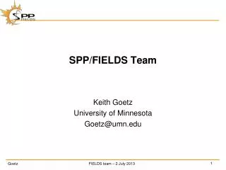
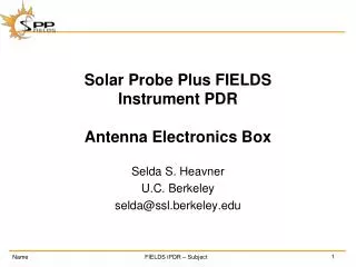
SPP-Fields Antenna Electronics Board (AEB)Concept Status Report J.W.Bonnell, S. Harris, S. Heavner Space Sciences Laboratory UC Berkeley (as presented by W. Rachelson) jbonnell@ssl.berkeley.edu sharris@ssl.berkeley.edu selda@ssl.berkeley.edu
Summary • Full time engineering support now available (Heavner), with part-time Science (Bonnell) and Systems (Harris) support as well for the AEB effort, so design progress is being made. • Close collaboration with PA design effort (Seitz, Bonnell, Goetz) to keep relevant interfaces (power, signal, noise) consistent. • Specification of breadboard (BB) AEB complete (1 channel – FGND, BIAS, STUB, SUN_SHIELD, +/- 100-V fixed, +/- 15-V floater). • AEB BB Design in progress (through Dec 2012): • Parts selection (switching supply drivers, DACs, bias output section transistors) • Schematic and bill of materials (BB and parallel 3DPlus packaging effort)
Scope of AEB Design Effort • Antenna Electronics Board (AEB, see following block diagram slide) • FGND Driver: • 1 channel each for 4 forward whips. • 1 channel for aft whip or dipole (TBR). • Sensor bias current, Stub and Shield bias voltage drivers: • 4 channels of each for 4 forward whips. • 1 channel of TBD subset for aft whip or dipole. • Whip preamp bias range relay control: • 1 channel each for 4 forward whips. • TBD channel for aft whip or dipole. • Floating and HV output stage Power Supplies: • 2 floaters to support opposing pairs of forward whips. • 1 floater (TBR) to support aft whip or dipole. • 1 HV (+/- 100-V) supply to support FGND and bias driver output stages. • Serial Command and Data (HSK) I/F to ICU. • Preamp-to-AEB Harnessing (TBR). • AEB-to-DFB Harnessing in MEB (TBR).
AEB – Block Diagram Replace with simple serial interface to ICU. CAL deleted. Floaters (1/axis) and HV NOT part of estimate for proposed AEB (assumed part of LNPS). Possible Channel 5 to support 3rd axis/tail sensor.
AEB – Power Service Concept • AEB uses existing switching supply designs (THEMIS, RBSP). • There will be changes to magnetics to accommodate changes in driver frequencies and SYNC requirements. • AEB takes regulated, filtered supplies from LNPS and providing following supplies: • ± 100-V supply (bias output stages). • ± 12-V analog (AEB input stages). • ± 15-V floaters (LF-PA supplies).
AEB Requirements (Dec 2012) • Preamp signal characteristics • DC voltage level: ± 60Vdc w.r.t. AGND (THEMIS-EFI-BEB) • AC voltage level: ± 10V w.r.t. floating ground (± 13V capability; RBSP-EFW-PRE) • Floating Ground Driver • Input: LF Preamp signal • Input filter roll off: 500 Hz (TBR; RBSP-EFW-BEB) • Output voltage level: ± 60Vdc w.r.t. AGND • Floating supply rails: ± 15Vdc (RBSP-EFW-BEB, -PRE) • Bias, Stub, Shield Drivers • Reference Input: LF Preamp signal • Reference input filter roll off: 500 Hz (TBR; RBSP-EFW-BEB, match FGND) • Output voltage level: Vref ± 40Vdc (max, programmable) w.r.t. AGND • DAC resolution: 16-bit (TBR; RBSP-EFW-BEB, THEMIS-EFI-BEB) • Max voltage required: ±100V (THEMIS-EFI-BEB and IDPU-LVPS) • Noise voltages at Bias, Stub, and Shield outputs consistent with noise floor requirements and predicted coupling to antenna (TBD).
Challenges and Plan for AEB Design Effort • Adapting existing THEMIS (BEB, LVPS) and RBSP-EFW (PRE) designs for SPP environments, resources, and requirements (all Phase B): • Equallychallengingradiation environment than THEMIS or RBSP, but less mass resources available for shielding: • Compile initial BOM, review against TID and SEE, and re-select parts as needed. • More functionality (bias control AND power supply) to pack into same or smaller PWB area, mass and power allocation than THEMIS, RBSP (and MEL values!): • Prepare initial layout using elements of existing designs to prove fit to PWA area. • Determine realistic mass and power estimates from elements of existing designs to refine mass and power impact of design options (e.g. 3rd axis measurement). • Consider and evaluate alternate part types (e.g. SMD rather than through-hole 100-V transistors) to trade change in design against mass/power/thermal benefits. • Demonstrating DC-LF compatability with MF and HF noise floor requirements: • HF noise floor requirements are one or two orders of magnitude more strict than THEMIS or RBSP: • Build breadboard channel, including floater and HV supplies using existing flight spare parts/hardware to allow for noise generation/succeptability testing and prove concept design will meet noise floor requirements at antenna (Phase B/early Phase CD).
AEB – Mass Estimates (June 2012) • Floating and HV supply mass impact significant – minimum two-axis system is almost twice the mass carried in the proposal MEL! • Mass estimate needs to be refined with reference to THEMIS 100-V system, rather than RBSP-EFW 225-V system based on design decisions from June 2012.
AEB – Power Estimates (June 2012) • BEB power consumption can be significant. • Power estimate needs to be refined with reference to THEMIS 100-V system, rather than RBSP-EFW 225-V system based on design decisions from June 2012.