Download
1 / 56
570 likes | 745 Views
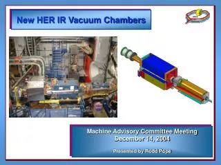
New HER IR Vacuum Chambers. Machine Advisory Committee Meeting December 14, 2004 Presented by Rodd Pope. New HER IR Vacuum Chamber Team. Q4R/Q5R – Don Arnett & Albert Sheng Q4L/Q5L – Ted Osier & Rodd Pope Q4/Q5 Bellows - Nadine Kurita & Manuel Trigos Support from Ho Dong

E N D
New HER IR Vacuum Chambers Machine Advisory Committee Meeting December 14, 2004 Presented by Rodd Pope
New HER IR VacuumChamber Team • Q4R/Q5R – Don Arnett & Albert Sheng • Q4L/Q5L – Ted Osier & Rodd Pope • Q4/Q5 Bellows - Nadine Kurita & Manuel Trigos • Support from Ho Dong • Managed by Nadine Kurita
Location BSC & Luminosity Stay Clear Synchrotron Radiation & Heat Loading Beam Position Monitors Supports HER Q4/Q5 Bellows Module NEG Antechamber Screen Design and Fabrication Milestone Schedule Outline
HER- Downstream, “Forward”, “Right” 9.4M 8.4M 5.7M 0.0 M 19.5M 2.3M 3.6M High-Power Dump Frangible Link Q5R Q4R Q2R IP e- HER- Upstream, “Backward”, “Left” 0.0 M 3.6M 2.3M 7.7M 8.5M 10.1M 11.4M 5.7M IP Q2L Q4L Q5L Frangible Link “Luminosity Chamber” 10M Collimator
Design SpecificationBeam Parameters • Maximum HER beam energy/current: • 9 GeV at 2.2 Amps “Farther Future” per M. Sullivan • Maximum LER beam energy/current: • 3 GeV at 4.5 Amps • Beta *s for HER & LER • Beta x* = 28 cm • Beta y* = 7 mm “Farther Future” per M. Sullivan • Emittances for HER & LER • Emittance x = 60 nm-rad • Emittance y = 24 nm-rad
Beam Stay Clear • Beam Stay-Clear • HER BSC: +/- 12x x 9y • Luminosity Cone: 6.24 • BSC through Q2R is • +/- 12x x 8.5y 6.24s Luminosity Cone Q2L Outboard Flange Looking Toward IP 12sx x 9sy BSC
Q4 HER BSCOutboard Magnet End Looking Toward IP 12sx x 9sy BSC Q4L Q4R Luminosity Cone (6.24s) ~90% Clear
Q5 HER BSCOutboard Magnet End Looking Toward IP 12sx x 9sy BSC Q5L Q5R Luminosity Cone (6.24s) ~85% Clear
Luminosity Clear Ray • Limiting Aperture is Frangible Link • Green Line Represents Clear Aperture • Green Line Clears Q5L & Q4L BSC Luminosity Luminosity Chamber Frangible Link Q5L
SR, I2R & HOM Heat Loads • HER @ 9 GeV at 2.2 Amps • LER @ 3 GeV at 4.5 Amps • HOM & I2R Engineering Guess = 269 W/m • Re-analyze at 1 kW/m (worst case estimate) • 10% Reflected SR Power
Heat Load Summary • Q5R May Intercept B1L & B1R High Power SR During Mis-steer • Actively Safe Chamber (TC Interlocked) • Uniform Heating from HOM and I2R Loads • Balanced Cooling to Minimize Dynamic (Thermal) Bowing • Q5L & Q4L Intercepts B3, B2 & BLF HER SR • Distribute SR Power Over H20 Cooled, Aluminum Chamber Wall • Distributed Masks Allow Larger BSC than Discrete Masks • Balanced Cooling to Minimize Dynamic (Thermal) Bowing
e- Q4R SR Ray Tracing • Q4R is clear. Q4R Looking Toward the IP
65 inches B1 SR e- Q5R Beam Missteering Location Q5R Looking upbeam • Add additional cooling channels to eliminate uncertainty of HOM induced thermal gradient within missteering region. • It is the worst case when B1 (R) and B1 (L) SR strike at the same spot. • Active safe when using thermocoupleto detect transient temperature rise.
Locations of Thermocouples Water channel Thermocouples, 1/8” deep, 3/8” equal spacing B1(L) B1( R) Possible missteering area Combined 0.5 mrad horizontal and 1 mrad vertical mis-steering. Water channel Looking upbeam
Transient Analysis due to Beam Missteering Trip stress = 25ksidTmax = 97 C Trip stress = 30ksidTmax=116 C dT at thermocouple = 30 C dT at thermocouple = 14 C
LER SR Into Q4L HER • Plot Frame Represents Chamber Walls • B1L & B1R SR Rays
LER SR Through Q45L HER Bellows • Plot Frame Represents Chamber Walls • All B1L & B1R Rays
LER SR Through Q5L • Plot Frame Represents Chamber Walls • All B1L & B1R Rays
Q5L HER Chamber • Chamber analyzed • 0 W of LER SR • 2560 W of HER SR (B3, B2, BLF) • 269 W/m HOM (517 W) • Tmax = 36 C • max = 13 KSI (combined thermal and mechanical stress). • Re-analyze with 1 kW/m HOM, 10% reflected power and displacement loads from installation and manufacturing tolerances.
Q4L HER Chamber • Chamber analyzed • 0 W of LER SR • 591 W of HER SR (B3, B2, BLF) • 269 W/m HOM (430 W) • Tmax = 25 C • max = 3.7 ksi (combined thermal and mechanical stress). • Re-analyze in 3D with 1kW/m HOM, 10% reflected power and displacement loads from installation and manufacturing tolerances.
Thermal and Mechanical Loading • Temperature, thermal induced deformation and stress: *On may conclude that overall chamber deformation and stress are vacuum force dominated. Max. y deform Max. y deform vacuum vacuum Max. x deform Max. x deform HOM + I2R HOM + I2R Q4R Q5R
Beam Position Monitors • 2 Sets of 4 PEP LER Arc Type, Bolt-in BPM’s • No Additional Sets are Being Added • Located Immediately Outboard of Q4 and Q5 Magnets • Chamber Geometry to Optimize BPM Signal-to-Noise Ratio • Supporting Chamber at BPM location to the Magnet • Bellows allows locking Q5 BPM’s in Z • Increases accuracy and stability
e- e- Beam Position Monitor (BPM) Q4R looking downbeam Q5L looking downbeam
BPM 4” bellow Q4R Q5R Q5R Q4R Q2R Q2R Q4R s1 Q5R s1 Q5R s1 Q4R s1 Q5R s2 Old Design New Design Supports BPM e -
Supports • Addition of Bellows Increases Degrees of Freedom • Fix Q5 HER Chambers in X, Y & Z at BPM • Isolate Any Thermal Induced Loads in Q5 • Reduce Any Thermal Induced Loads in Q4
Q4/Q5 Bellows Module • HER arc bellows concept + absorbing tile in bellows cavity. • Nadine to discuss in detail. Q4 side, 10” flange Inconel Spring Finger Absorbing Tile GlidCop Stub GlidCop RF Shield Finger Welded Bellows Q5 side 12” flange Cooling – not shown
Q5 HER NEG Anti-chamber Screen • New Screen Design • 3 mm diameter holes through 6 mm thick wall on a 4 mm center-to-center square pattern • Isolate NEG Wafers from HOM Power Allowing Net Pump versus Net Outgassing • Effective Pumping 695 L/s
Basic Chamber Design(Q5L HER Shown) Machined, Welded Aluminum Clamshells Explosion Bonded Al to SST Flanges PEP LER Arc Type BPM’s Machined Pump Screen NEG Assembly with Heater Rod (Q5R and Q5L HER Only) Variable Wall Thickness to Balance Strength, Magnet Clearance and Beam Clearance
Status • All Chambers through Preliminary Design Review • All Driving Requirements Have Been Identified • Preparing Drawings for Long Lead Items • Preliminary Machined Half Estimates Received • Completing Final Analysis to Support Final Design Review
Milestone Schedule • Final Design Review – 1/05 • Order Long Lead Items – 1/05 • Complete Piece Part Drawings - 3/05 • Procurements - 3/05 • Receive Long Lead Items – 4/05 • Receive components, inspection - 6/05 • Weld/assemble, Clean and Bake - 7/05 • Chambers Ready for Installation - 9/05
Q4/5L Clear Luminosity Ray • Limiting Aperture is Frangible Link • Green Line Represents Clear Aperture • Green Line Clears Q5L & Q4L Q5L Magnet Corrector Magnet Q4L Magnet
Installation and Servicing • Final alignment in tunnel vacuum chamber tolerances are: • Local alignment (4 chambers TBD) • X- and Y-tolerance = ± 125 m (.005"). • Z-tolerance = ± 1.5 mm (.098"). • Pitch and Yaw = ± 1.0 mrad (.06°). • Global alignment • X- and Y-tolerance = ± 250 m (.009"). • Q4 to Q5 chamber X or Y offset across Bellows Module < 0.05". • Absolute accuracy of chamber manufacturing tolerances • ± 2 mm full width in X (TBD) • ± 2 mm full height in Y (TBD)
Q4 & Q5 Vacuum Chamber Requirements • Improve alignment and thermal motion of chambers. • Maintain gap between chamber and magnet • 2 mm minimum between chamber and pole tip, • 3 mm minimum between chamber and coil. • Reduce thermal gradient in chambers • Change material to Al with water cooling. • Add bellows • Reduces reaction forces on chamber supports/raft from thermal distortion. • Reduces reaction forces on chamber supports/raft from current design due to manufacturing tolerances (pitch, yaw). • Addition of a flex flange would further reduce load on the raft supports, but space constraints make a new design difficult. • Minimize changes to the raft for support modifications.
BPM’s • Beam Position Monitors (BPM’s) • Use spare PEP-II BPMs for Al chambers • One set at the outboard end of Q4 and one set at the outboard end of Q5. • Support the BPM set in x and y. Hold in z only if it doesn’t compromise other requirements. • BPM’s are centered on the beam in the x-direction, • Q5L chamber has a BPM center to BPM center x-direction spacing of 1.875” (R. Johnson, S. Smith (2004). • Q5R & Q4 chambers has a BPM center to BPM center x-direction spacing is TBD. • Place BPM’s on flat surfaces. Avoid transitions. • Keep the BPM’s as far away from any holes and masks (at least 4 to 6”). • Buttons recessed .012” +/- .009”
BPM (cont.) • Support BPM to Quad magnet • No calibration required – QMS/BBA • BPM electrical centerline positional requirements with respect to quad magnetic centerline: • X- and Y- position absolute offset: ± 0.040". • Z-position absolute accuracy: ± 0.060". • Stability • X- and Y- long-term stability (precision): ± 0.001". • 3 hour time span - motion due to beam current, diurnal temperature, cooling water temperature, beam off/on hysterisis. Does NOT include drift of electronics. • Z long-term stability (precision): ± 0.010". • X- and Y- short-term stability (precision): ± 0.0005". • 1 minute time span - motion due to mechanical vibration of chamber with respect to quad magnet (not of magnet itself). Does NOT include jitter of electronics. • Z short-term stability (precision): ± 0.005"
Pumping • Pumping • Improve average pressure in the chamber (1 e-9 Torr). • Keep NEG in Q5 HER and maximize pumping conductance within screen dimensions. • Improve the screen to reduce broadband impedance and TE leakage into the pump. New Q5 HER screen dimensions: 3 mm (.118”) diameter holes thru 6 mm thick wall, 4 mm x 4 mm square center-to-center pattern. • Add noble diode ion pump at the outboard end of Q5R (TBD). • Add hot filament gauges, new RGA (TBD).
Fabrication Tolerance • Chamber length tolerance = ± 0.04" • Roll/Twist of chambers • Max allowable twist flange to flange is 3 mrads. This corresponds to a 0.020" step between Q4 & Q5 chambers. • Pins in bellows will allow for a 3 mrad of roll offset between flange pairs. • Chambers allow for 3 mrad of twist for manufacturing tolerances without applying an excessive load to the supports.
Supports • Q4 inboard flanges supported in x, yy, z by the Q2 chamber support. • Q4 outboard flange supported in xx, y to the raft or magnet? BPM precision will not be as stable as ones held rigidly. • Q5 inboard flange support in xx, y to the raft or magnet; or supported in xx, y, z. • Q5 outboard flange support in xx, y, z to the raft or magnet; or supported in xx, y. If held rigidly here than BPM stability is improved. Do we need to improve how the BPM is held here? Should we support to the magnet or to the raft or to the concrete pier? • Supports utilize rod ends and are fully adjustable in the field. UNC • Max X or Y deflection under operational loads = ± xxx" • Loading at Base of Support (Technical note, xxxx):
Vacuum Pressure • Average arc pressure ≤ 3.4 x 10⁻⁹ torr (N2 equivalent). • Average arc base pressure ≤ 5 x 10⁻¹⁰ torr • Peak pressure of any bump in profile = 5 x 10⁻⁷ torr (N2 equivalent). • Operating parameters: • 9 GeV on 2.2A HEB (CDR, p308) • ecrit = 9.8 keV at 9 GeV beam energy (CDR, p309) • Vacuum Calculation Variables • Copper & Aluminum • hphoto = 2 x 10⁻⁶ mol/photon (CDR, p310) • hphoto = 5 x 10⁻⁵ mol/photon (CO, Foerster) • htherm = 2 x 10-12 torr-L/cm2-s, scaled with temperature (CDR, p310): • htherm = 4.0 x 10⁻¹² @ 35°C (beam off) • htherm = 1.04 x 10⁻¹¹ @ 60°C (beam on) • No detectable gas species above mass 44 - measured by RGA.
Photodesorption Data C. Foerster
Running Parameters/Orbit Error • Design Running Parameters: • Fill time = 6 minutes, minimum, (0 to 3 amps HER or 4.5 amps LER). • Full cycles = 10,000 cycles over 20 years , (0 to 3 amps HER or 4.5 amps LER). • Fill cycles = 200,000 cycles, 80% to 100% current (3 Amps HER or 4.5 amps LER), over 20 years. • Max axial beam orbit distortion/steering error (CDR, p 304) • ± 7 mm in X. • ± 3 mm in Y. • Max angle beam orbit distortion/steering error (S. Ecklund). • ± 0.5 mrad in X. • ± 1 mrad in Y. • Design using a safety factor of 2 for the bellows and elsewhere when possible.
Heat Loading • Synchrotron radiation (SR) power • Chamber ends, SS flange pairs and bellows stubs must be shadowed by a nominal and mis-steer SR strike. • The RF Seal fingers and Bellows Module shield fingers need to be shadowed from a nominal SR strike and a mis-steer strike with a safety factor of 2. • Secondary back-scatter from SR. • Assume 10% of SR power is scattered onto chamber walls. • In HER arc dipole magnet, 11.6 % of SR is back-scattered off main strike surface. Outside of the field 12.2 % is back-scattered (FLUKA calculations summary by Al Lisin).
Goal of the Review • Approval of chamber design specification. • Approval of chamber design concept and material selection. • Proceed to final design, final design review and detail drawings. • Approval to procure long lead items. • GlidCop • Transition material • Bellows • Tiles