Download
1 / 1
10 likes | 108 Views
A study on three male NCAA Division I shot putters analyzing their hip and shoulder orientations using a motion tracking system. Results show unique kinematics for each thrower.

E N D
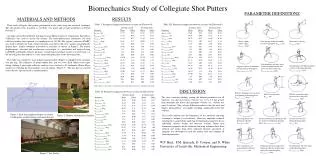
Biomechanics Study of Collegiate Shot Putters PARAMETER DEFINITIONS MATERIALS AND METHODS RESULTS Hip orientation Shoulder orientation Table I. Parameter comparison between sessions for Thrower #1. Table III. Parameter comparison between sessions for Thrower #3. Three male collegiate shot putters participated in the study using the rotational technique. The shot putters were classified as excellent, very good, and average performers in NCAA Division I. • An eight camera Hawk Motion Tracking System (Motion Analysis Corporation, Santa Rosa, California) was used to record the motion. The three-dimensional coordinates for each reflective marker were captured at a sampling rate of 100 Hz. The system’s software (EVaRT) was used to identify the body surface locations associated with each marker and graphically display these marker coordinate trajectories in real-time, as shown in Figure 1. The marker displacements, velocities and accelerations were output to a spreadsheet and analyzed using LabVIEW and Matlab software packages. A right hand coordinate system was used with x as the throwing direction and the x-y axes representing the plane of the throwing circle. The study was conducted in an indoor training facility (Figure 2) equipped with an indoor shot put ring. The collegiate 16 pound indoor shot put was used. Each subject wore tight-fitting clothing. Lightweight reflective markers were attached to 24 landmarks, Helen Hayes marker set excluding the head markers, on each subject.(Figure 3). The shot putwas covered with reflective tape and used as another marker. Shot x-z plane release angle, qrelease_xz(deg) Foot spacing during the middle part of sweep phase, dfeet_90o (m) Shot release velocity, Vrelease_xz (m/s) Non-dominant side knee angle when non-dominant side foot leaves the back of the ring, qnon-dom_knee_takeoff (deg) Non-dominate side hip maximum velocity in throwing direction, Vmax_non-dom_hip_x(m/s) Angular velocity of dominant side leg during sweep phase, wmax_dom_leg_sweep(r/s) Abbreviations: take-off (to), touch-down (td), thrusting position (tp), dominant-side (dom). DISCUSSION Table II. Parameter comparison between sessions for Thrower #2. Relative dominant side arm angle at beginning of thrusting phase, qhumerus-torso_tp (deg) Relative separation angle between torso and pelvis, qtorso/pelvis_max (deg) Shot release position, hrelease(m) The most consistent finding, among the defined parameters for all throwers, was that shot release velocity was 1.5 to 2.5 m/s greater than dominant side distal ulna maximum velocity (i.e., velocity just prior to release). This velocity difference indicates that the wrist and fingers, during release, are capable of adding significantly to the shot velocity. Figure 1. Real-time graphical display of motion tracking data acquired during rotational shot put. Figure 3. Thrower with markers attached. The results indicate that the kinematics of the rotational throwing technique is unique to each thrower. However, important technical information is gained from analyzing the kinematic parameters for an individual thrower within and between sessions. Many new kinematic parameters of the rotational throwing technique have been defined and results from three collegiate throwers presented. A program was developed to read the marker data and compute all defined parameters. First step distance of dominant side foot, ddom_first_step(m) Distance between non-dominant side toe and toe board during thrusting phase, dnon-dom_foot/toe_board (m) Distance between feet during thrusting phase,dfeet_tp (m) W.P. Hnat, P.M. Quesada, D. Cowper, and N. White University of Louisville, Mechanical Engineering First step distance of non-dominant side foot, dnon-dom_first_step(m) Dominant side knee angle when dominant side foot touches ring during the transition phase, qdom_knee_td(deg) Non-dominant side foot angle during thrusting phase, qnon-dom_foot_tp(deg) Figure 2. Test facility.