Download
1 / 22
220 likes | 237 Views
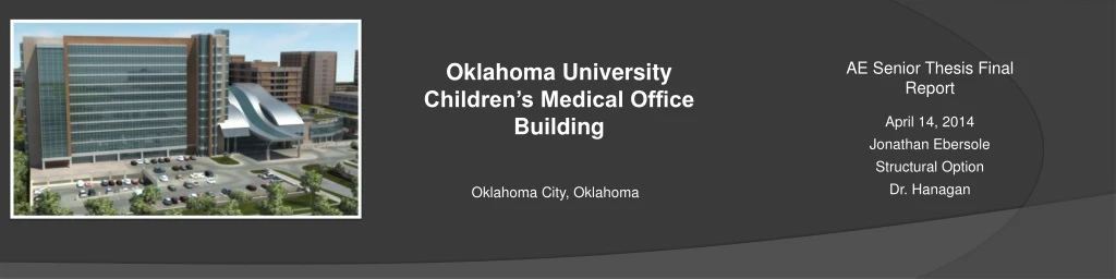
This report outlines the proposal for a structural and architectural redesign of the Oklahoma University Children's Medical Office Building, aiming to reduce costs, shorten the schedule, and maintain the building's architectural integrity.

E N D
Oklahoma University Children’s Medical Office Building AE Senior Thesis Final Report April 14, 2014 Jonathan Ebersole Structural Option Dr. Hanagan Oklahoma City, Oklahoma
Introduction • Building Statistics • Project Team • Existing Structure • Proposal • Structural Depth • Architectural Breadth • Construction Breadth • Conclusion Building Statistics • Location: 1200 North Children’s Avenue, Oklahoma City, Oklahoma • Occupancy: Office • Size: 320,000 gsf • Height: 12 stories for a total of 172 ft. • Construction Dates: February 2007- Spring 2009 • Building Cost: $59,760,000 • Delivery Method: Design-Bid-Build
Introduction • Building Statistics • Project Team • Existing Structure • Proposal • Structural Depth • Architectural Breadth • Construction Breadth • Conclusion Project Team • Owner: University Hospitals Trust • Construction Manager: Flintco, Inc. • Project Architect: Miles Associates • Structural Engineer: Zahl-Ford Inc. • MEP Engineer: ZRHD, P.C. • Civil Engineer: Smith, Roberts, Baldischwiler, Inc.
Introduction • Building Statistics • Project Team • Existing Structure • Proposal • Structural Depth • Architectural Breadth • Construction Breadth • Conclusion Existing Building Structure Typical Bay Gravity • Reinforced, cast-in-place concrete • Foundations • Drilled piers, spread footings, and grade beams • Two way flat slab system with drop panels • 10” slab with 4” drop panels • Exterior Beams 26’ 32’
Introduction • Building Statistics • Project Team • Existing Structure • Proposal • Structural Depth • Architectural Breadth • Construction Breadth • Conclusion Existing Building Structure Lateral Layout Lateral • Reinforced cast-in-place concrete shear walls • Located in stairwells, elevator shafts, and center of floor plan • Typically 12” thick • Moment frames located along the floor plan perimeter N
Introduction • Proposal • Problem Statement • Depth Introduction • Breadth Introduction • Structural Depth • Architectural Breadth • Construction Breadth • Conclusion Problem Statement • Reduce overall building costs • Reduce the schedule duration • Develop an economical steel system • Maintain a low impact on the building architecture http://www.metalconstructionnews.com/articles/columns/high-flying-inspiration.aspx
Introduction • Proposal • Structural Depth • Design Loads • RAM Model • Composite Steel Redesign • Steel Joist Redesign • Lateral System Redesign • Drift Comparison • Architectural Breadth • Construction Breadth • Conclusion Design Loads Gravity Loads Lateral Load Base Shears • Wind E-W controls
Introduction • Proposal • Structural Depth • Design Loads • RAM Model • Composite Steel Redesign • Steel Joist Redesign • Lateral System Redesign • Drift Comparison • Architectural Breadth • Construction Breadth • Conclusion RAM Model • Model Assumptions • Columns are considered as pinned connections at the base • Wind Loads are to be applied at the center of pressure • Each floor diaphragm is considered rigid N
Typical Bay • Introduction • Proposal • Structural Depth • Design Loads • RAM Model • Composite Steel Redesign • Steel Joist Redesign • Lateral System Redesign • Drift Comparison • Architectural Breadth • Construction Breadth • Conclusion Composite Steel Floor Redesign • Typical Bay • 1.5 VLR 22 gauge composite deck • 3 ¼” lightweight topping • Unshored, 3 span construction • Beams • W14x22 with 20 studs and a 1” camber • Girders • W16x31 with 38 studs and a ¾” chamber • Beams, girders, and columns are to be fireproofed for a two hour fire rating N
Introduction • Proposal • Structural Depth • Design Loads • RAM Model • Composite Steel Redesign • Steel Joist Redesign • Lateral System Redesign • Drift Comparison • Architectural Breadth • Construction Breadth • Conclusion Steel Joist Roof Redesign • Typical Roof Bay • Typical Bay • 1.5 B 22 gauge roofing deck • Unshored, 3 span construction • Joists • 24K9 joists • Girders • W18x40 • Roof deck, joists, girders, and columns will be fireproofed for a two hour fire rating N
Introduction • Proposal • Structural Depth • Design Loads • RAM Model • Composite Steel Redesign • Steel Joist Redesign • Lateral System Redesign • Drift Comparison • Architectural Breadth • Construction Breadth • Conclusion Lateral System Redesign Lateral System Layout • Concentric, diagonal braced frames • Located in existing shear wall locations • Consists of square HSS steel tubes • Additional moment frames are needed • Located along the eastern wall • Moment frames where used to minimize the impact on the architecture Concentric Braced Frames N Additional Frames
Drift Comparison • Introduction • Proposal • Structural Depth • Design Loads • RAM Model • Composite Steel Redesign • Steel Joist Redesign • Lateral System Redesign • Drift Comparison • Architectural Breadth • Construction Breadth • Conclusion Building Drift Under Controlling Case • Existing concrete lateral system drift: 4.77 inches • Proposed steel lateral system drift: 4.75 inches • IBC 2009 allowable building drift: 4.98 inches N
Introduction • Proposal • Structural Depth • Architectural Breadth • Plant selection • Material Selection • Impact on Structural System • Green Roof Cost Analysis • Construction Breadth • Conclusion Plant Selection • Oklahoma City hardiness zone: 7a and 7b • Identifies the appropriate plants for a specific environment • Sedum plants are used • Hardy plants that can survive a variety of different environments • Can grow in shallow soil depths • Ability to resist droughts Sedum Floriferum http://macgardens.org/?m=201306 Sedum Oreganum http://www.greatcity.org/
Introduction • Proposal • Structural Depth • Architectural Breadth • Plant selection • Material Selection • Impact on Structural System • Green Roof Cost Analysis • Construction Breadth • Conclusion Material Selection • Growing Medium • RoofliteExtensive MCL • Filter Fabric • Green Roof Solutions FF35 • Drainage Panel • Green Roof Solutions GRS 32 Image obtained from http://www.vegetalid.us/green-roof-systems/green-roof-101/what-is-a-green-roof
Introduction • Proposal • Structural Depth • Architectural Breadth • Plant selection • Material Selection • Impact on Structural System • Green Roof Cost Analysis • Construction Breadth • Conclusion Material Selection • Root Barrier • Green Roof Solutions RB20 • Waterproof Membrane • Kemper System Kempero 2K-PUR • Rigid Insulation • DOW Building Solutions Highload 60 Insulation • Vapor Barrier • Roof Aqua Guard BREA Image obtained from http://www.vegetalid.us/green-roof-systems/green-roof-101/what-is-a-green-roof
Introduction • Proposal • Structural Depth • Architectural Breadth • Plant selection • Material Selection • Impact on Structural System • Green Roof Cost Analysis • Construction Breadth • Conclusion Impact on the Structural System • Initial dead load estimation for the green roof was 30 psf. • The total dead load for the green roof is 22 psf • The estimated dead load is conservative compared to the actual dead load
Introduction • Proposal • Structural Depth • Architectural Breadth • Plant selection • Material Selection • Impact on Structural System • Green Roof Cost Analysis • Construction Breadth • Conclusion Green Roof Cost Analysis • Green roofs have a higher initial costs compared to a standard built up roof • Using RS Means Cost Construction Data, the total additional cost for the green roof is $412,000.00
Introduction • Proposal • Structural Depth • Architectural Breadth • Construction Breadth • Cost Comparison • Schedule Comparison • Conclusion Cost Comparison • Detailed cost analysis using RS Means for each system • Original concrete design estimate: $9,055,000.00 • Proposed steel design estimate: $5,125,000.00 • Cost is significantly reduced
Introduction • Proposal • Structural Depth • Architectural Breadth • Construction Breadth • Cost Comparison • Schedule Comparison • Conclusion Schedule Comparison • Schedule determined from RS Means • Original Concrete System • Assumed three crews to decrease schedule times • 710 days to complete • Proposed Steel System • Assumed one crew erecting the steel • 189 days to complete http://www.projsolco.com/portfolio/healthcare-imaging-solutions
Introduction • Proposal • Structural Depth • Architectural Breadth • Construction Breadth • Conclusion • Design Conclusion • Acknowledgements • Questions Design Conclusion Goals Results • Reduce overall building costs • Reduce the schedule duration • Develop an economical steel system • Maintain a low impact on the building architecture • Redesign was more cost effective • The schedule time was reduced • Composite steel with unshored construction • Steel provides an open floor plan • Lateral system has little impact of exterior facade
Introduction • Proposal • Structural Depth • Architectural Breadth • Construction Breadth • Conclusion • Design Conclusion • Acknowledgements • Questions Acknowledgements • University Hospitals Trust • Miles Associates • Zahl-Ford Inc. • Department of Architectural Engineering • Friends and Family
Introduction • Proposal • Structural Depth • Architectural Breadth • Construction Breadth • Conclusion • Design Conclusion • Acknowledgements • Questions Questions?


