
Basic Terms
E N D
Presentation Transcript
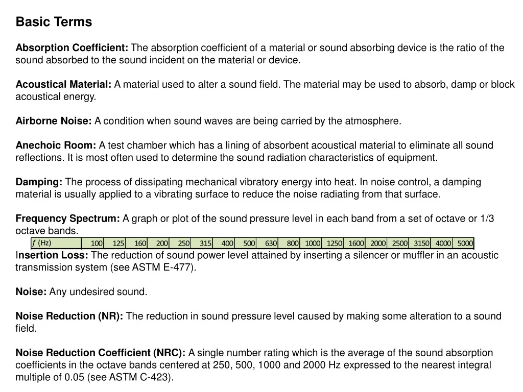
Basic Terms Absorption Coefficient: The absorption coefficient of a material or sound absorbing device is the ratio of the sound absorbed to the sound incident on the material or device. Acoustical Material: A material used to alter a sound field. The material may be used to absorb, damp or block acoustical energy. Airborne Noise: A condition when sound waves are being carried by the atmosphere. Anechoic Room: A test chamber which has a lining of absorbent acoustical material to eliminate all sound reflections. It is most often used to determine the sound radiation characteristics of equipment. Damping: The process of dissipating mechanical vibratory energy into heat. In noise control, a damping material is usually applied to a vibrating surface to reduce the noise radiating from that surface. Frequency Spectrum: A graph or plot of the sound pressure level in each band from a set of octave or 1/3 octave bands. Insertion Loss: The reduction of sound power level attained by inserting a silencer or muffler in an acoustic transmission system (see ASTM E-477). Noise: Any undesired sound. Noise Reduction (NR): The reduction in sound pressure level caused by making some alteration to a sound field. Noise Reduction Coefficient (NRC): A single number rating which is the average of the sound absorption coefficients in the octave bands centered at 250, 500, 1000 and 2000 Hz expressed to the nearest integral multiple of 0.05 (see ASTM C-423).
Octave Band (O.B.): A range of frequencies where the highest frequency of the band is double the lowest frequency of the band. The band is usually specified by the center frequency, i.e., 31.5, 63, 125, 250, 500 Hz, etc. Reverberation Room: A test chamber so designed that the reverberant sound field within the room has an intensity that is approximately the same in all directions and at every point. It is commonly used to measure sound absorption, ASTM C-423 and transmission loss, ASTM E-90. Sound: Pressure waves that are traveling in the air or other elastic materials. Sound Absorption: The acoustical process whereby sound energy is dissipated as heat rather than reflected back to the environment. Sound Power Level (Lw): A measure of the acoustic power generated by a noise source, expressed on a decibel scale Sound Pressure Level (Lp): A measure of the air pressure change caused by a sound wave, expressed on a decibel scale Sound Transmission Class (STC): A single number rating derived from measured values of transmission loss in accordance with ASTM 413. The rating provides an estimate of the performance of a barrier in certain common noise attenuation applications. Structure-borne Noise: Mechanical vibration in a structure which can ultimately become audible sound. Until such time as radiation occurs, these vibrations are inaudible and of little concern. Transmission Loss (TL): The reduction in sound power that is caused by placing a wall or barrier between the source and receiver. Transmission loss is expressed in decibels.
Product Classification • Absorber • Barrier • Damper • Composite
Absorbers • Absorbers reduce sound by absorbing the energy of the sound waves and dissipating them as heat.
Barriers • Barriers perform a blocking function to the airborne sound. Barrier performance is dependent on frequency and is most effective at high frequencies. The effectivity of barriers dependents on their mass and stiffness.
Damper • Damper is defined as a treatment to reduce the vibrations.
Composite • Combination of absorbers and barriers to create desired NVH performance
Absorption Materials • Sound is absorbed when it encounters a material which will convert some or all of it into heat, or which allows it to pass through not to return. • Absorptive materials are generally fibrous,porous or in rather special cases reactive resonators
Factors influencing sound absorption of non-woven materialsFactors influencing sound absorption of non-woven materials Fiber size Fiber surface area Airflow resistance Porosity Tortuosity Thickness Density Surface treatment Absorption Materials
Absorption Materials Fiber size • Decrease in fiber diameter increases sound absorption coefficient
Absorption Materials Fiber surface area • Sound absorption increases with specific surface area of fiber • Non-round (trilobal, pentalobal, etc.) fibers can provide improved sound absorption compared to round fibers
Absorption Materials Airflow resistance • Interlocking fibers in nonwovens are the frictional elements that provide resistance to acoustic wave motion • Due to friction the acoustic energy is converted into heat
Absorption Materials Porosity • Defined as the ratio of the volume of the voids in the material to its total volume • Sound must be able to enter a porous material. There must be sufficient pores on the surface of the material for the sound to get through and get damped
Absorption Materials Tortuosity • Measure of the elongation of the passage way through the pores, compared to the thickness of the sample • Determines the high frequency behavior of sound absorbing porous materials
Absorption Materials Thickness • Low frequency sound absorption has direct relationship with increased thickness • Absorption at higher frequencies is less impacted by thickness
Absorption Materials Density • Sound absorption increases in the middle and high frequencies as density of the material increases • Less dense materials have better absorption at lower frequencies
Absorption Materials Surface treatment • Additon of treatments increase of sound absorption at low frequencies at the loss of higher frequencies • Sometimes, fibrous materials are covered with film in order to improve the sound absorption properties at low frequencies
Absorption Materials • Sound absorptive materials are chosen according to the spectrum of the sound being emitted. • For example in automotive noise control, thinner materials that are capable of absorbing high frequencies are used for headliners. At the same time, thicker materials capable of absorbing lower frequencies are used for door panels and carpet backing • It is essential to know the range of frequencies that need to be controlled in order to have effective use of sound absorptive materials
Required specification for product Acoustic data – measurement in Kundt Tube (NAC) and in situ measurement (SPL) as well Flammability – FMVSS 302 (TL 1010) Temperature resistant – for different types of product Color, UV stability Dust Other VDA norms
System Analysis Component Analysis Panel Selection Material Specification OEM ProvidesVehicle NVH Targets • Material Spec • Frequency Range XX.X • Peak Damping Temperature XX.X • Viscoelastic Core Material MSC XX • Thickness XX.X • Composite Loss Factor XX.X • Complex Modulus XX.X System Validation Materials Engineering Manufacture Solution Vehicle Validation Component Validation Engineering Process Automotive example shown is typical for all market segments
Supply Chain • Raw material • Produce non-woven fiber material • Cut/trim to appropriate shape • Apply to carrier part (where applicable) • Install on end item • Check acoustic performance of final product
Segmentation of Insulation Materials EPS expanded XPS extruded
A lightweight acoustic insulation insulation materials from thermally bonded fibre of various densities and thicknesses are available in rolls, cut and perforated pads, or pressed shapes. • compression moulding • three-dimensional shapesfrom acoustic materials. Three-dimensional moulding gives consistent performance and achieves different densities and thicknesses • thermal lamination of various films, fabrics and
Forms of Insulation Materials Plates (e.g. FG, rockwool) – precut thick layers of nonwoven fabric sheets Rolls – continuous rolls made of thick layers of nonwoven fabric sheets Loose-fill (e.g. cellulose - may also be wet-sprayed, expanded vermiculite)can be blown into attics, finished wall cavities, hard-to-reach areas (conform to spaces and fill in the nooks and crannies) – applied using a mechanical blowing machine also can be sprayed in place (usually with water-based adhesives)often made of recycled materials, relatively cheap Spray foams (e.g. synthetic polymers) Rigid panels – made from fibrous materials (e.g. FG, rockwool, slagwool) or plastic foamStructured panels (SIPs – Structural Insulated Panels)composite building material - sandwich of two layers of structural board (usually OSB) with an insulating layer of foam (EPS, XPS, PUR) in between
Used Materials & Applications *kapota kabiny **kapota motoru ***palubní deska Audible frequency 20 Hz to 20 kHz 2 Automotive designers worry about sounds ranging from 800 Hz to 3 kHz(e.g. combustion engines emit frequencies from 100 Hz to 8 kHz -> no single insulating material can block all of those frequencies -> combination of materials can be effective)
Factors Influencing the Choice of Material Technical and socioeconomic factors durability - resistance to compression, moisture, degradation cost of the material - generally related to durability and effectiveness resistance to extreme environment conditions (extreme temperatures, industrial chemicals, lubricants, moisture can reduce the life of the insulation the safety characteristics of the material and its insulating gas(flammability, toxicity, etc.) thickness - the thinner insulator– the better ease of installation helps keep costs low in any application - material that can be compressed Environmental factors if it is recycled or destroyed... resources – particularly energy- efficiency other environmental impact (on water, air ..)
Material Share by Revenues2005 USA = 80% revenues Canada = 20% revenues Synthetics are replacing the shoddy materials owing to superior acoustical control and lightweight. FG - also some replacement due to safety, but it has high heat resistance and good sound insulation, which make it difficult to replace (e.g. the hoodliner)
Examples of material composition This material is specially designed composite for engine noise reduction. It consists of a hydrolysis resistant acoustic foam with polyurethane film facing to protect the acoustic foam from contaminations such as oil, dust and fluids and a flexible high mass noise barrier with non-woven backing. The barrier material is a PVC-based polymer alloy loaded with minerals. It increases transmission loss and sound absorption. Product is designed for maximum noise insulation of engine noise insulation (125Hz – 2000Hz);
EXAMPLE OF DASH MAT LAYER CONSTRUCTION HEAVY LAYER ACOUSTIC BATTING CARPET
Polyester Sound Absorber with Fireproof Sound Absorbing Facing and Self-adhesive Backingsound absorption material consists of an fireproof sound absorbing facing and environmentally friendly acoustic polyester-wool. The facing non flammable. It has high temperature resistance up to 550°C. Traditional fireproof facing materials have little or zero acoustic properties. Combined with the thermally bonded acoustic polyester-wool , the material provides high sound absorption at low to mid frequencies. Material range has three standard thicknesses: 25mm , 50mm and 100mm.
Acoustic Absorption Testing (Alpha Cabin, impedance tube, reverberation room) Sound absorption is an important property of automotive interior components because it measures how effectively sound is dissipated once it enters the interior, which affects the overall sound level. When a sound wave strikes a surface, a fraction of the acoustic energy is absorbed and the remainder is reflected. The ratio of absorbed energy to incident energy averaged over all possible angles of incidence is the Sabine absorption coefficient (or simply the absorption coefficient) of the surface. The Sabine area is the absorption coefficient multiplied by the actual surface area. The absorption coefficient is measured by placing a sample in a reverberation room, start and stop a sound source and measuring the resulting sound field decrease.
Alpha Cabin Testing The Alpha Cabin is a reverberation room that is used to measure the random incidence sound absorption of materials and parts. The test is similar to ASTM C423 but in a smaller room. The Alpha Cabin has approximate dimensions of 1.2 m x 1.6 m x 1.8 m with nonparallel walls. Nonparallel walls force the reflecting sound waves that produce the modes (standing waves) to reflect from all the walls in the room. Thus, a sample placed on the floor will affect the decay time of all of the modes. The Alpha Cabin equipment tests the sample, one third-octave band at a time. The sound field decrease is measured and recorded at each of five microphone positions. This process is repeated for frequency spectrum from 400 Hz to 10,000 Hz. The absorption coefficient is calculated from the average of five measured decreases for each frequency.
Impedance Tube Testing An impedance tube is used to test material samples for normal incidence sound absorption according to ASTM E1050, “Standard Test Method for Impedance and Absorption of Acoustical Materials Using A Tube, Two Microphones and A Digital Frequency Analysis System.” In an impedance tube, a loudspeaker is mounted at one end and a material sample is placed at the other end. The loudspeaker generates random sound waves which propagate as plane waves in the tube and are reflected off of the sample. The sound pressure is measured at two microphone locations and the transfer function between the two measurements is calculated. From this information, it is possible to determine the complex reflection coefficient, the sound absorption coefficient and the normal acoustic impedance of the material. The usable frequency range depends on the diameter of the tube and the spacing between the microphone positions. Generally it can provide measurements from 100 Hz to 1,600 Hz, as well as from 500 Hz to 6,400 Hz.
Transmission Loss Testing (reverb/anechoic room) The acoustic transmission loss test apparatus measures the attenuation of sound through a material sample or part. Sound transmission loss measures how effectively a material performs as a sound barrier. This is an important function for acoustic insulation materials and parts. The acoustic transmission loss test apparatus consists of a reverberant source chamber with an aperture into an anechoic chamber in which the sample is mounted. The sound transmission loss of each sample is measured per ASTM E90. Inside the reverberation chamber, acoustic source noise is introduced. The sound field is then measured at several different locations. The average of these measurements is recorded as the source sound pressure. Microphones are then used to measure the transmitted sound field on the other side of the sample. The difference between the source sound pressure, obtained as described above, and the sound power through the sample is the transmission loss of the sample. The measurement range is third-octave bands from 250 Hz to 10,000 Hz.
Insertion Loss Testing (APAMAT chamber) The APAMAT measures the noise radiation from an acoustic material treatment when subjected to a structural vibration input. In the APAMAT, a sample is placed on a sheet of steel similar in thickness to an automobile body. Ball bearings impinge against the bottom of the steel sheet to provide random structural excitation. The sound pressure is measured in a reverberation chamber sealed to the top of the sample. Third octave band sound pressure measurements are made with and without the sample on the steel sheet, and the difference is the APAMAT insertion loss for the sample. The results provide a combined measure of transmission loss, structural damping, and radiation efficiency and are useful for rank ordering sound package treatments.
Airflow Resistance Measurement System The sample holder permits the rapid and easy installation of the measurement samples. The sample is supported by a fine grid below the sample.
Figure 2 Block Diagram of Apparatus (Compressed Air operation)
Description The CARE+ (Concentric Airflow Resistance Evaluator) is an apparatus, which is designed to measure non-destructively the airflow resistance of materials and parts in the range 200 to 4000 Ns/m3. The apparatus comprises a vacuum pump and air flow meter and manometer. A probe is connected to this via two 2 metre long tubes. This probe is placed over the sample to be measured. The airflow resistance of the sample may then be calculated directly from the pressure difference read from the manometer.
The probe comprises two concentric cylinders as shown in the diagram. The vacuum pump draws air through both of these cylinders.