Download
1 / 48
850 likes | 1.77k Views
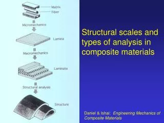
Subject: Composite Materials Science and Engineering Subject code: 0210080060. Prof C. H. XU School of Materials Science and Engineering Henan University of Science and Technology Chapter 8: Ceramic Matrix Composites (CMCs). Ceramic Matrix Composites (CMCs). This chapter will cover

E N D
Subject: Composite MaterialsScience and Engineering Subject code: 0210080060 Prof C. H. XU School of Materials Science and Engineering Henan University of Science and Technology Chapter 8: Ceramic Matrix Composites (CMCs)
Ceramic Matrix Composites (CMCs) This chapter will cover Introduction to CMCs Fabrication of CMCs Review of selected CMCs Toughening mechanisms
Introduction to Ceramic Matrix Composites (CMCs) • Ceramics: high strength, stiffness, and brittle • Objective for CMCs is to increase in the toughness • Use and fabricate CMCs at high temperature • Less reinforcements are available Schematic force-displacement curves for a monolithic and CMCs, illustrating the greater energy of fracture of the CMCs
Introduction to Ceramic Matrix Composites (CMCs) Matrix materials Alumina Glass Carbon Reinforcement materials SiC B4C Carbon
Processing Ceramic Matrix Composites (CMCs) • Conventional mixing and pressing • (a) A powder of the matrix is mixed with reinforcement (particles or whiskers) together with a binder • (b) Pressure • (c) Fire or hot pressure • Difficulty during fabrication • Difficult to obtain uniform mixture • Damage to whiskers during mixing and pressing operations
Processing Ceramic Matrix Composites (CMCs) Slurries (泥浆) Simplified flow sheet (流程图) for mixing (whiskers or chopped fibers) as a slurry prior to shaping The properties of CMCs produced by slurries is not good because of more porosity in materials
Processing Ceramic Matrix Composites (CMCs) Slurries: for continuous fibre reinforced composite 1)Fibers (glass fibers), impregnated with slurry (powder glass (1-50mm) in water and water soluble resin binder), are wound on to a mandrel to form a tape. 2) The tape is cut into pies. 3) The types are stacked (lay-up). 4) Burnout of the binder 5) Heat pressure e.g. glass fiber reinforced glass-ceramic matrix)
Processing Ceramic Matrix Composites (CMCs) Liquid State Processing • Matrix transfer molding: glass matrix composite production CMCs with tube shape 1): SiC cloth (reinforcement) and glass slug (matrix) plunge in a cylinder 2) Heat to melt glass, press liquid and inject in SiC cloth 3) Eject the mandrel and cylinder e.g. SiC reinforced glass-ceramic (polycrystalline structure) matrix
Processing Ceramic Matrix Composites (CMCs) • Sol-gel (溶胶-凝胶)processing • sol: dispersion of small particles of less than 100 nm, obtained by precipitation (沉淀) resulting from a reaction solution • Gel: sol lost some liquid to increase viscosity Pour sol over perform (reinforcement) Mix sol or gel with reinforcement Repeat infiltration and dry until required density dry Dry sol heat to produce required ceramic Hot press Fire Mixing reinforcement in a sol or a gel Infiltration of a preform e.g. ZrOCl2+NH3+3H2O=2NH4Cl+Zr(OH)4 Zr(OH)4 → ZrO2 at 550℃
Processing Ceramic Matrix Composites (CMCs) • Vapor deposition techniques e.g. TiCl4(g)+2BCl3(g)+5H2(g) = TiB2(s) + 10 HCl(g) SiCl4(g) + CH4(g) = SiC (s) + 4HCl(g)
Processing Ceramic Matrix Composites (CMCs) Lanxide process • Formation of a ceramic matrix by the reaction between a molten metal and a gas (e.g. molten aluminum reacting with oxygen to form alumina) • growth rate is • parabolic when the diffusion of liquid metal controls the process. • linear when chemical reaction at preform and infiltrated preform controls process; In this case, liquid metal diffuses rapidly by a wicking (灯芯的) process along grain boundaries in ceramic matrix when gsv> 2gsL.
Review of selected CMCs- SiC reinforcement alumina Usually made by slurry method (SiC whisker and polycrystalline a-alumina)
Review of selected CMCs- SiC reinforcement alumina • left fig. showing: Improvement in toughness due to SiC whiskers in alumina matrix at various temperature • Right fig. showing: Log-log plot of strain rate versus stress showing that the creep rate at a given stress is less for the SiC reinforced alumina
Review of selected CMCs- SiC reinforcement alumina SiC whisker reinforced alumina has good thermal shock (热冲击)resistance. The reasons are • lowers the coefficient of thermal expansion; • Increase the thermal conductivity; • Improves the toughness; Thermal shock behaviors of an alumina-20vol%SiC whisker composite and alumina; cooling materials from high T to room T in water
Review of selected CMCs- Zirconia-toughened alumina • Zirconia, ZrO2, -toughened alumina (ZTA) contains reinforcement (10-20vol% of fine Zirconia) and matrix (alumina). • ZrO2 Crystal: • Tetragonal (T) at high temperature • Monoclinic (M) at low temperature • T→M transformation during cooling causes an increase in 3% volume, producing microcrack in Al2O3 matrix. • Microcracks absorb energy to improve toughness of composite
Review of selected CMCs- Zirconia-toughened alumina • Add stabilizing oxide, such as 3mol.% Y2O3 to ZrO2 suppress t→m transformation during cooing. • Fine metastable tetragonal-ZrO2 at room temperature in ZTA • ZrO2 particles at a crack tip will transfer to monoclinic-ZrO2 under stress, which is called as transformation toughing.
Review of selected CMCs- Glass-ceramic matrix composites • Glass-ceramics: some glass with crystal structure • E.g. lithium aluminosilicate (LAS) system • Working temperature: LAS-I 1000℃; LAS-II 1100℃; LAS-III 1200℃;
Review of selected CMCs- Glass-ceramic matrix composites Young’s modulus of SiC-LAS composites is larger than monolithic LAS
Review of selected CMCs- Glass-ceramic matrix composites Composites have higher strength than that of monolithic LAS • Elastic deformation at beginning (linear curves) • Matrix plastic deformation and reinforcement elastic deformation. • Reinforcements break from point F
Review of selected CMCs- Glass-SiC reinforcements Room temperature Toughness of LAS-SiC composite
Review of selected CMCs- Glass-SiC reinforcements • The properties of composite maintained to 1000℃ in inert atmosphere. • The properties of composite reduced from 800 ℃ in air. Oxygen diffuses along microcracks in the matrix and reacts with SiC.
Unidirectional reinforcement -glass matrix composite has better fatigue properties • Cross-plied reinforcement glass matrix composite has less fatigue properties.
Review of selected CMCs- Carbon – Carbon Composites Dense carbon-carbon composites • Continuous fiber materials • the good mechanical properties of the better quality of fiber • Produce a materials with a desired degree of anisotropy (各向异性) • Discontinuous fiber materials • Being used to fabricate large components • produce isotropic materials and improve inter-laminar strength • Applications: disc brakes for racing car and aircraft, gas turbine components, nose cones and leading edges for missiles
Review of selected CMCs- processing dense carbon-carbon composites Manufacture a Preform Continuous discontinues carbon fibers, mats Preform • Manufacture Matrix (dense treatment) • Liquid phase process • Chemical vapour infiltration Thermosetting resins, Pitch hydrocarbon C-C composite (mesophase carbon matrix) Graphitization C-C composite (graphite matrix) Oxidation resistance treatment C-C composite with a protective layer
Dense carbon-carbon composites-Manufacture a reinforcement preform Continuous and discontinues carbon fibers, mat Reinforcement preform
Dense carbon-carbon composites-Manufacture matrix • Liquid phase processing • Raw materials - thermosetting resins (phenolic, furan, polymide, polyenylene) : • Impregnation (注入) thermosetting resins in a reinforcement preform • ~ Polymerize at 250℃ to form cross-link polymer • Pyrolysis (高温分解)and carbonization at 600~1000℃ to form amorphous, isotropic carbon (carbon yield about 45~80%) • Raw materials - Pitch: • Impregnation pitch in a reinforcement preform • thermoplastic polymer in nature • Pyrolysis and carbonize at 600~1000℃ to form a highly orientated mesophase carbon; carbon yield about 50% under normal pressure and up to 90% under high pressure • Each cycle needs about 3 days. • multiple impregnation and carbonization to obtain high density;
Dense carbon-carbon composites-Manufacture matrix • Chemical vapor infiltration (CVI) , also called as chemical vapor deposition: thermal decomposition of hydrocarbon, such as methane CH4(g) = C(s) + 2H2(g) under suitable temperature and pressure • Laminar aromatic (芬芳的) • Layered pyrolitic carbon • Isotropic sooty (乌黑的) • surface nucleated dense pyrolitic graphite • continuously nucleated graphite
Dense carbon-carbon composites-Manufacture matrix • Isothermal method: • The infiltration (渗透): under low pressure of 0.6 ~ 6 MPa at a constant temperature of 1100℃. • Problem: form an impermeable crust (外壳) • The crust must be removed by a machine to remain continuous infiltration. • Thermal gradient method: • The infiltration carried out under atmosphere pressure at a inner temperature of 1100℃. • The inner of sample was heated by induction coil. • Pressure gradient method: • Gas is forced into the interior of samples
Dense carbon-carbon composites- graphitization and coating • Graphitization: heat treatment at high temperature up to 1500~2800℃ to obtain graphite matrix • coating • In order to Improve oxidation resistance of composite • A coating system capable of offering protection up to 1400℃ currently; • Coating must be satisfy • Mechanically, chemically and thermally compatible with the composite • Adhere to the composite • Prevent diffusion of oxygen from the environment through to the composite • Prevent diffusion of carbon from the composite to the environment • Complex protective systems • Large differences in the coefficient of thermal expansion (CTE) between coating layer and composite during cooling lead to cracking of coating and loss of oxidation protection. • SiC and Si3N4 as primary oxidation barrier coat, based on CTE. • Second protective system: add a glass former particles in to matrix to form glass phase or having an additional glass coating.
Dense carbon-carbon composites- Properties The effects of different carbon matrix on the properties of C-C composite
Dense carbon-carbon composites- Properties 1-D (one dimensional woven carbon fibre reinforced composite) is strong but brittle. 2-D (two dimensional woven carbon fibre reinforced composite) has properties intermediate to those of the 1-D and 3-D 3-D (three dimensional woven carbon fibre reinforced composite) has better toughness and less strength The low toughness of 1-D composite is attributed to the poor interlaminar properties Schematic stress-strain curves illustrating the effects of the form of reinforcement on strength and toughness
Dense carbon-carbon composites- Properties • Comparison of the fatigue performance of carbon fiber reinforced carbon composite and carbon fiber reinforced polymer composite: (a) torsion; (b) flexural • Fatigue property of CFRC is similar to CFRP
Dense carbon-carbon composites- Properties Specific strength versus temperature for ACC: made using woven carbon cloth; RCC: produced from low modulus fiber; High strength C-C: made with unidirectional carbon fibers interplied with woven cloth
Review of selected CMCs- Porous carbon – carbon Composites Porous carbon-carbon composites, also called as carbon bonded carbon fibres (CBCF) • Processing: • A mixture including carbon fiber, phenolic resin (binder), and water; • The mixture pumped into a mould; • Water extracted under vacuum and dry • Carbonization at ~950℃, carbon yield about 50%, • Graphite at high temperature to obtain 99.9% carbon. • porosity contents are in the range 70-90% • Application of CBCF as insulation at high temperature under vacuum (no oxygen) or at the temperature less than 400℃
Review of selected CMCs- Porous carbon – carbon Composites • Strength related to the density • The properties are anisotropic. • Fiber orientation takes place under vacuum during processing Strength of carbon bonded carbon fiber as a function of density and orientation. Z and X/Y denote the direction of the tensile stress in the bend test
Toughening mechanisms- Introduction • There are many different toughening mechanisms. • One or more toughening mechanisms may operative in a composite. • The effectiveness of the toughening mechanisms depends on: • Size, morphology and volume fraction of the reinforcement; • Interfacial bond; • Properties (e. g. mechanical, thermal expansion) of the matrix and the reinforcement; • Phase transformation • ……
Toughening mechanisms- crack bowing (弓) Crack bowing • (a) Crack approaches to reinforcements. • (b) the crack bowed under stress to form a nonlinear crack front. • Decrease in the stress intensity K along the bowed section in the matrix • Increase in the stress intensity K at the reinforcement • K reached to the fracture toughness of the reinforcement → the reinforcement breaks • Bowing needs more energy to increase toughness
Toughening mechanisms- crack bowing • Crack bowing toughing ↑ • with ↑ the volume fraction of reinforcement (more reinforcements) • with ↑aspect ratio of the reinforcement • with ↑the properties of reinforcement
Toughening mechanisms- Crack deflection (偏斜, 偏转) • Crack deflects and becomes non-planar, due to interaction between the reinforcement and crack front. • (a) Tilt (倾斜)of crack front • (b) Twist (扭) of crack front • There are 3 crack modes • Flat crack propagates in mode I. • Tilt crack in modes I and II • Twist crack in modes I and III
Toughening mechanisms- Crack deflection • Deflection occurs when the interaction of the crack with the residual stress fields due to differences in the thermal expansion coefficients or elastic moduli between the matrix and reinforcement. • Deflection toughening ↑: • with↑volume fraction of reinforcement • With ↑ aspect ratio of reinforcement • Dominated by twisting rather than tilting of the crack
Toughening mechanisms- Debonding toughening • Debonding: Reinforcement fibre separates from matrix. • Debonding toughening: New surface in the composite require energy in debonding. • Debonding toughening ↑ • Weak interface of matrix and reinforcement • Strong reinforcement • Large volume fraction of reinforcement.
Toughening mechanisms- Pull-out toughening • Pull out a fibre • Pull-out • Debonding • Fibre fracture for long fiber • The normal (法线)frictional forces have to be overcome during pull-out. • The maximum pull-out length of a fibre is ½ the critical length (lc). • If embedded length is greater than lc. fibre will break.
Toughening mechanisms- Pull-out toughening • Maximum work to pull out a fibre is Where D, lc and sTf are diameter, critical length and fracture strength of the fibre, respectively. • The energy of pull-out is greater than that of debonding. Pulling a fibre out of the matrix
Toughening mechanisms- Fibre bridging toughening • Fibre bridging: some fibres debonds but not break. • Fibres carry out stresses under load. • Reduce the stresses at crack tip and hinder crack propagation. • Toughness-crack extension curve: • Toughness increase with crack extension at initial cracking • Constant toughness maintains when crack reaches to critical value.
Toughening mechanisms- Microcrack toughening • Thermal stress forms between matrix and reinforcement during cooling, due to difference in coefficient of thermal expansion (a). • af>am • Tangential compressive and a radial tensile stresses in matrix • Circumferential crack forms under high tensile stress. • af>am Tangential tensile stress in matrix cause radial crack under high tensile stress. Stress distribution and microcrack formation around spherical particles when (a) af>am, (b) af<am,C and T for compressive and tensile stresses
Toughening mechanisms- microcrack toughening • The toughness of a materials can be enhanced by the presence of microcracks, due to crack blunting, branching and deflection. • The microcrack toughening is effective on the limited density and size of cracks. • Toughness of materials increases and strength decreases in the microcrack toughening.
Toughening mechanisms- Transformation toughening • Metastable tetragonal-ZrO2 at room temperature in ZTA • transformation toughing: ZrO2 particles at a crack tip will transfer to monoclinic-ZrO2 under stress. Energy is absorbed ahead of the primary crack owing to the transformation. • Giving an increase in toughness △KTT = 0.3vzirc △eEmro1/2 Where vzirc is the volume fraction of metastable particles; △e is unconstrained strain accompany the transformation; Em is young’s alumina matrix and rois the width of zone in the crack. • Strength and toughness of materials increase at same time. Transformation toughening: transformation of metastable particles at the crack tip gives a Zone, of width ro, of transformed particles
Further Reading: Text Book: Composite Materials: Engineering and Science (pages118-160, 326-356). Reference book: Introduction to Materials (page 241-283) Other reference: Lecture note 8