Download

1 / 29
300 likes | 446 Views
LCWS04, Paris. Scintillator Tile Hadronic Calorimeter Prototype (analog or semidigital) M.Danilov ITEP(Moscow) CALICE Collaboration. O utline. Granularity required for Particle Flow Method Silicon Photomultiplier (SiPM) Optimization of Tile Fiber System

E N D
LCWS04, Paris Scintillator Tile Hadronic Calorimeter Prototype (analog or semidigital) M.Danilov ITEP(Moscow) CALICE Collaboration
Outline • Granularity required for Particle Flow Method • Silicon Photomultiplier (SiPM) • Optimization of Tile Fiber System • Experience with MINICAL production (108 channels) • Preparation of Physics Prototype • Conclusions
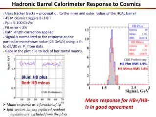
LC Physics goals require DEJ/√EJ~30% This can be achieved with Particle Flow Method (PFM): Use calorimeter only for measurement of K,n, and g Substitute charged track showers with measurements in tracker LC detector architecture is based on PFM, which is tested mainly with MC Experimental tests of PFM are extremely important We are building now a prototype of scintillator tile calorimeter to test PFM
Longitudinal segmentation more important
Separation can be further improved by optimization of algorithm
SiPM main characteristics • Pixel size ~20-30mm • Electrical inter-pixel cross-talk minimized by: • decoupling quenching resistor for each pixel • boundaries between pixels to decouple them • reduction of sensitive area • and geometrical efficiency • Optical inter-pixel cross -talk: • due to photons from Geiger discharge initiated by one electron and collected on adjacent pixel • Working point: VBias = Vbreakdown + DV ~ 50-60 V • DV ~ 3V above breakdown voltage • Each pixel behaves as a Geiger counter with • Qpixel = DV Cpixel • with Cpixel~50fmF Qpixel~150fmC=106e • Dynamic range ~ number of pixels (1024) • saturation 42m 20m pixel h Resistor Rn=400 k Al R 50 Depletion Region 2 m Substrate Ubias
SiPM Spectral Efficiency • Depletion region is very small ~ 2mm • strong electric field (2-3) 105 V/cm • carrier drift velocity ~107 cm/s • very short Geiger discharge development < 500 ps • pixel recovery time = (Cpixel Rpixel) ~ 20 ns • Photon detection efficiency (PDE): • - for SiPM the QE (~90%) is multiplied by Geiger efficiency (~60%) and by geometrical efficiency(sensitive/total area ~30%) • highest efficiency for green light • important when using with WLS fibers • Temperature and voltage dependence: • -1 oC +3% in Gain * PDE • +0.15 V +3% in Gain * PDE WLS fiber emission
20 40 one pixel gain (exp. data) one pixel gain (linear fit) , % =565nm) detection efficiency ( l e 15 30 5 10 20 One pixel gain M, 10 Efficiencyof light registration 5 10 operating voltage 0 0 0 1 2 3 4 5 6 , V Overvoltage U=U-U D U =48V breakdown breakdown Photon detection efficiency = QEgeom
SiPM signal saturation due to finite number of SiPM pixels : ,pixels Average number of photoelectrons for central tiles for 6 GeV Very fast pixel recovery time ~ 20ns For large signals each pixel fires about 2 times during pulse from tile
SiPM Noise random trigger noise rate vs. threshold 1p.e. 2p.e. Ped. 3p.e. 1p.e. noise rate ~2MHz. threshold 3.5p.e. ~10kHz threshold 6p.e. ~1kHz Optimization of operating voltage is subject of R&D at the moment.
Comparison of the SiPM characteristics in magnetic field of B=0Tand B=4T (very prelimenary, DESY March 2004) LED signal ~150 pixels A=f(G, , x) No Magnetic Field dependence at 1% level (Experimental data accuracy)
Long term stability of SiPM • 20 SiPMs worked during 1500 hours • Parameters under control: • One pixel gain • Efficiency of light registration • Cross-talk • Dark rate • Dark current • Saturation curve • Breakdown voltage No changes within experimental errors 5 SiPM were tested 24 hours at increased temperatures of 30, 40, 50, 60, 70, 80, and 90 degrees No changes within experimental accuracy
(Y11 MC 1mm fiber, Vladimir Scintillator, mated sides, 3M foil on top and bottom ) Reduction near tile edges is due to finite size of a b source Light Yield from Tiles with Circular WLS Fibers 5x5x0,5cm3 16x16x0.5cm3 Sufficient uniformity for a hadron calorimeter even for large tiles Can be further improved if required Sufficient light yield of 17, 28, 21 pixels/mip for 12x12, 6x6, and 3x3 cm2 tiles (quarter of a circle fiber in case of 3x3 cm2 tile)
Experience with a small (108ch) prototype (MINICAL) Moscow Hamburg SiPM Tile with SiPM cassette 3x3 tiles
Light Yield from Minical tiles (5x5x0.5cm3) Using triggered Sr source and LED at ITEP LED b N pixel Using electron beam at DESY (SiPM signals without amplification) Good reproducibility after transportation from Moscow to Hamburg
Cross-talk measurement • - Conditions: 50 mm tiles with mated edges, - source, 2mm collimator. • Red points: 3M film on top and bottom of both tiles; • blue points: black paper instead of 3M for tile 1. • Right picture: details of top and bottom of the left one. • - Conclusion: Cross talk <1% I Tile 1 Tile 2 PM scanning millimeters
SiPMs will be tested and calibrated with LED before installation into tiles (noise, amplification, efficiency, response curve, x-talk) PC driven generator LED driver Remote control 16 channel power supply Steering program DATA BASE ……. gate Tested SiPM .. X~100 16 ch 12 bit ADC 16 ch amp 16 ch 12 bit ADC Scheme of test bench for SiPM selection at ITEP
Tiles will be tested with a triggered β source and LED before installation into cassette Test bench for tile tests at ITEP 16 ch 12 bit ADC 16 chan amps gate 16 ch remote control power supply Steering program b -source 16 sci tile plane step motor trigger counter DATA BASE movable frame discriminator
All tiles in the cassette will be tested before transportation to DESY Final tests and commissioning with FE electronics and DAQ will be done at DESY Cassette with Tiles and Electronic Cards
CONCLUSIONS Particle Flow Method requires high granularity especially longitudinally Scintillator tiles with WLS fiber light collection and SiPM mounted directly on tiles can be used to build highly segmented hadronic calorimeter, which can be used in analog or semidigital mode Tests of 108 channel prototype (MINICAL) demonstrated effectiveness and robustness of this technique Seven thousand channel calorimeter prototype with tiles in the core as small as 3x3 cm2 is being constructed now. It will be ready for tests next year. Hcal prototype together with Ecal prototype will allow to to test experimentally the Particle Flow Method
Scintillator strips with WLS fiber and SiPM readout can be used for muon system and shower position detectors in electromagnetic calorimetersScan of Strip Using Cosmics Setup at ITEP groove depth 2.5mm LED cosmics Center of strip, N pixels (peak) = 9.7 from each side ∑ PoissXtalk·G(x0+i·Δx,0+1 ·√i)
Scan of Strip Using Cosmics Setup at ITEPLight yield was corrected for cosmics angular distribution and interpixel cross talk in SiPM Poisson mean for MIP at normal incidence for a strip 200x2.5x1cm3 Sum Left SiPM Right SiPM Large number of p.e. leads to high efficiency >99.9 Technique for a compact,efficient and simple in operation muon detector
Emission Spectrum of Y11 WLS Fiber Measured at distances 10cm, 30cm, 100cm and 300cm from source.
Amplitude Dependence on Temperature T=+9.5oC T=+14.6oC T=+20.1oC T=+25.3oC