Download
1 / 15
150 likes | 174 Views
This project aims to provide pion-muon separation and deflect the beam away from the small angle photon veto, using a magnetized hadronic calorimeter and muon veto. The design includes detectors, dipole magnets, drift chambers, and a liquid krypton calorimeter, along with a proposed magnetized hadronic calorimeter and muon veto system.

E N D
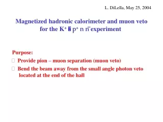
Magnetized hadronic calorimeter and muon veto for the K+ p+n n experiment L. DiLella, May 25, 2004 • Purpose: • Provide pion – muon separation (muon veto) • Bend the beam away from the small angle photon veto located at the end of the hall
7.2 cm muons from pion decay (few % of p+ flux) detector axis 2 cm diam. beam spot; centre 3.52 cm from detector axis • Detector elements as in Niels’ geometry file (k12hika.txt): • Blue tube starts at z = 102.2 m • Kevlar window at z = 203.8 m (~ 12.2 m upstream of present position) • Double spectrometer with two identical MNP33 dipole magnets 12.6 m apart • pT kick = ± 0.21 GeV/c (in opposite directions ) • Six Drift Chambers (assumed to be identical in shape, performance and resolution to the present ones) • Liquid Krypton calorimeter untouched – cryostat ends at z = 242.9 m • Small angle photon veto near the end of the hall ( z = 257 m) Beam spot after the second dipole magnet p+ flux : 1.5x10 9 per spill
A problem with the photon veto LKr cryostat Additional photon veto photon shower detected in LKr beam photon shower NOT detected in LKr beam pipe Liquid Krypton Hadronic calorimeter front face Need additional photon veto behind LKr and increase of beam pipe diameter
Criteria for the design of the hadronic calorimeter and muon veto • An important background from K+m+ nm decay: • “catastrophic” muon energy losses • muon bremsstrahlung • e+e- pair production • high Q2m+ e- scattering • muon decay in flight • deep inelastic muon – nucleon scattering m+ + N m+ + hadrons electromagnetic shower • Integration with LKr calorimeter • Distinguish hadronic showers from electromagnetic showers need longitudinal and lateral segmentation • Sensitivity to minimum ionizing particles (MIP) • Bending power ~ 4.5 T x m pT kick 1.35 GeV/c deflects 75 GeV/c beam by 18 mr (18 cm lateral displacement at 10 m) In general, the outgoing m+has enough residual energy to be detected
Acceptance forK+ p+n n decay “Toy” MonteCarlo includes: • beam momentum spread s(p)/p = 1%, no angular spread • gaussian multiple scattering and chamber resolution (tuned on measured Kpp+p- mass resolution in NA48/2) • K+ decay region from blue tube entrance to kevlar window • parametrization of LKr energy resolution (with gaussian shape) Results agree with G. Ruggiero’s calculations using FLYO (see 10.05.2004) Measurement of p+ momentum: weighted average of the measurements from the two magnets; angle with respect to beam axis given by DCH1+2 Cuts: 14 <pp< 4 0 GeV/c (Missing Mass)2 MM2 in two separate regions (to exclude K+p+ p): 0 < MM 2< 0.01 GeV 2 (Region I) 0.026 < MM 2< 0.068 GeV 2 (Region II)
Results from 107 simulated K+ p+ n n decays p+ momentum (GeV/c) MM2 (GeV2) Region I Accepted events after p+ momentum cut: Region I: 5. 9 % Region II: 17.1 % Region II
Distribution of accepted p+ on the front face of LKr y (cm) 250x250 cm2 area x (cm)
Proposed magnetized hadronic calorimeter and muon veto 150 Iron plates 2 cm thick Rectangular hole 30 x 22 cm Weight of each plate 1126 kg 1.5 cm gap between plates Total length 5.25 m Front face at z = 243.5 m (0.6 m behind LKr cryostat) 4 vertical coils instead of 2 horizontal coils for full access to gaps between plates from the two sides (Niels’ suggestion) B = ~ 1.5 T in beam region ~ 8 m between calorimeter end and beam dump at the end of the hall
Plates are bolted together to top and bottom support plates Proposed longitudinal segmentation: three independent sections of 17 plates each One section : 19.3 x0 , ~2lint a reasonable matching to LKr ( ~ 25 x0 , ~2lint ) Gaps 52 through 132 are not instrumented The last 17 gaps are again instrumented to veto muons surviving catastrophic energy losses
Active detector material : Extruded polystyrene scintillator strips 130 cm long, 4 cm high, 1 cm thick read out by a single 1.2 mm diameter wave-length shifting fibre (as in the MINOS and OPERA experiments) Performance of MINOS strip 8 m long, 4 cm high, 1 cm thick Observe two fibre light attenuation lengths: l1 0.7 m, l2 3.9 m The 17 fibres from strips at the same y coordinate in one section go to a single 1 cm diam. PMT to form a calorimeter “cell” Scintillator is extruded with TiO2 white cladding and groove where fibre is glued In total: 130 strips per instrumented gap 2210 strips per section 130 cells 130 PMT’s per section 4 fully instrumented sections Vertical segmentation only (4 cm) For our case expect 4.5 photoelectrons per strip from a minimum ionizing particle
Calibration Calibrate LKr + hadronic calorimeter “in situ” by sending low intensity pion beams of variable energy to different points on the front face of LKr (another application of “Italo’s runs”) Expected energy resolution for hadronic shower ( Iron sections only): (as measured by MINOS) Need optimized algorithm to combine hadronic shower information from LKr and Iron calorimeter for optimal energy resolution Event rate in Hadronic Calorimeter Main contribution: K+ decays ( 2.4x10⁷ per spill ~ 5 MHz) Rate of hit cells (5 MHz / 130) xn 40 kHz xn n : number of hit cells per K+ decay ( n = 2–5 )
Pion selection and muon veto • Hadronic shower must start before Section 2 (LKr + Section 1 4lint) • E(shower) / track momentum 1 within calorimeter energy resolution • Reject tracks associated with an electromagnetic shower • Reject tracks associated with a m.i.p. signal in sections 2, 3 or 4 (the end section) Background from Km2 decays can be measured from the data themselves (events with m.i.p. signal in first 4 lint and late showers)
A simple example from the “Toy” MonteCarlo:Km2 decay followed by m decay in the calorimeters Track momentum distribution for K+ p+ n n signal is ~flat between 14 and 40 GeV/c 107 simulated K+ m+ nm decays 14 < track momentum < 40 GeV/c 555 events in Region I of the MM2 distribution (this number depends critically on momentum and angular resolution) MM2 assuming p+ mass (GeV2) Track momentum (GeV/c)
Muon decay in calorimeters E / p (including muon polarisation effects) Decay in LKr (E in GeV) Decay in Iron calorimeter Assumed resolution: (E in GeV)
Cost estimate • OPERA Proposal (CERN/SPSC 2000-028): • 144 6.7x 6.7 m2 scintillator planes ( 6464 m2 in total) • Each plane: 256 6.7 m long strips read out INDIVIDUALLY from both sides using 64-channel multi-anode PMTs • Total number of strips 36864 1152 64-channel multi anode PMTs • Estimated cost (including fibres and PMTs): kCHF 2200 • Proposed magnetized Iron Calorimeter: • 68 2.6x2.6 m2 scintillator planes ( 460 m2 in total) • Each plane: 1301.3 m long strips • Total number of strips 8840 read out in groups of 17 by 1 cm diam. PMTs • Total number of 1 cm diam. PMTs = 520 Estimated cost 0.1 x OPERA + cost of Iron