Download
1 / 28
290 likes | 400 Views
Explore how interrupts work in real-mode CPU operation, learn about interrupt requests, and understand the Interrupt Service Routine (ISR) process.

E N D
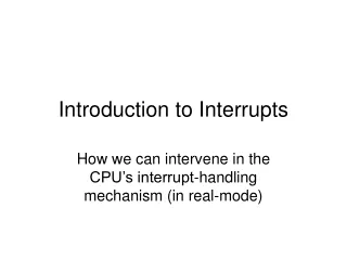
Introduction to Interrupts How we can intervene in the CPU’s interrupt-handling mechanism (in real-mode)
Recall ‘fetch-execute’ cycle • The processor repeatedly performs the following sequence of actions: • Fetch the next instruction (at address CS:IP) • Advance the instruction-pointer register (IP) • Decode the just-fetched instruction • Execute the just-decoded operation • But devices may interrupt this cycle (by raising a voltage on the INTR input-pin)
External Interrupt Requests CPU SMI# NMI EFLAGS INTR IF-bit As soon as the CPU has completed execution one instruction (and before it starts to execute the next one), it will sample the voltages on these input-pins. If it detects a signal on the INTR line, and if the IF-bit is set to 1 in the FLAGS register, then the CPU will defer executing the next instruction, and instead will transfer control to an Interrupt Service Routine (ISR).
Response to INTR • These are the actions taken by the CPU if it detects an INTR signal (while IF=1): • Push the FLAGS register onto the stack • Clear IF and TF bits in the FLAGS register • Push the CS and IP registers onto the stack • Query the PIC to obtain the IRQ ID-number • Lookup the corresponding Interrupt-Vector • Load CS and IP with the vector’s values
Interrupt Vector Table (IVT) 0x00 0x01 0x02 0x03 0x04 0x05 0x06 0x07 0x08 0x09 0x0A 0x0B 0x0C 0x0D 0x0E 0x0F 0x10 0x11 0x12 0x13 0x14 0x15 0x16 0x17 0x18 0x19 0x1A 0x1B 0x1C 0x1D 0x1E 0x1F 0x20 0x21 0x22 0x23 0x24 0x25 0x26 0x27 0x28 0x29 0x2A 0x2B 0x2C 0x2D 0x2E 0x2F 0x30 0x31 0x32 0x33 0x34 0x35 0x36 0x37 0x38 0x39 0x3A 0x3B 0x3C 0x3D 0x3E 0x3F 0x40 0x41 0x42 0x43 0x48 0x49 0x50 0x58 Here is the User Timer-Tick Interrupt-Vector (it’s the one we will temporarily modify to point at our own “custom” Interrupt Service Routine 0x60 0x68 0x70 0x78
An Interrupt Vector’s layout Each vector is a doubleword (4 bytes) Byte 1 Byte 2 Byte 3 Byte 0 OFFSET SEGMENT Least significant word goes into register IP Most significant word goes into register CS
Conditions on entering an ISR • Further device-interrupts are disabled • On the stack are saved IP, CS and FLAGS • All the other CPU registers are unmodified • The suspended program can be resumed, at the point where it was interrupted, using the CPU’s special ‘iret’ instruction • ‘iret’ pops the three topmost words off the stack and back into IP, CS, and FLAGS
Preserving interrupted context • It is vital for an interrupted program to be able to resume with exactly the same CPU state it had before being suspended • The CPU saves only a ‘minimal’ amount of the program-context (FLAGS, CS, and IP) • It’s a responsibility of the ISR programmer to save and restore any other registers it may be necessary to modify within the ISR
The IBM-PC ROM-BIOS • When the IBM-PC was introduced (1981), the full source-code for its ROM-BIOS was published (as a Technical Reference) • That code was written entirely in assembly language (for the 8086 processor) • It was approximately 5,400 lines in length • It included Interrupt Service Routines for each of the standard peripheral devices
An ISR example • One of the standard peripheral devices is the Programmable Interval-Timer (PIT) • During the Power-On Self-Test, the timer is programmed to generate an interrupt at regular intervals (approximately 18.2 times per second) • These ‘timer-tick’ interrupts are used for timekeeping purposes by the ROM-BIOS
Four timer-tick actions • By studying the IBM source-code, we see that four actions are performed each time the PIT generates a ‘timer-tick’ interrupt: • The double-word counter (located at 40:6C) gets incremented; if it reaches its maximum, it’s reset to zero and a ‘rollover’ flag is set. • The motor_wait counter (byte at 40:40) gets decremented; when it reaches 0, the floppy disk-drive motors, if on, are turned off
Timer ISR (continued) • A software interrupt (INT-0x1C) executes, to allow applications an easy method for implementing customized timing activities • A EOI-command (End-Of-Interrupt) is sent to the system’s Programmable Interrupt Controller (PIC) informing it that it’s now ok to activate requests for interrupts from the peripheral devices
An In-Class Exercise • We want to experiment with ‘hooking’ the user timer-tick interrupt (INT-0x1C) • By default the IVT contains an interrupt vector for INT-0x1C pointing to a ‘dummy’ interrupt service routine (just an ‘iret’) • We can overwrite this IVT entry with our own entry, a vector that points to a custom service-routine that performs some action we have designed (e.g., show time-of-day)
The bootsector ‘squeeze’ • As we know, there isn’t much room for us to include much custom code in a diskette boot-sector (only 512 bytes total) • But we CAN put code into a bootsector that will load lots more code, from other diskette-sectors, into the physical ram • This is how an operating system boots up • We can call the BIOS to read disk-sectors
INT-0x13 services • Six service-routines for floppy diskettes: • #0: reset the floppy diskette controller • #1: return status of diskette controller • #2: read sector(s) from floppy diskette • #3: write sector(s) to floppy diskette • #4: verify sector(s) on floppy diskette • #5: format a track on a floppy diskette • More details on Ralf Brown’s Interrupt List
1440KB Diskette organization Heads (2 per disk) Sector-size (512 bytes) Tracks (80 per head) Sectors (18 per track)
Terminology and Numbering • The Disk-Controller locates its data-blocks using a so-called CHR coordinate-system • Cylinders: 0..79 • Heads: 0..1 • Records: 1..18 • The floppy drives are numbered 0, 1, 2, …
How to read from diskette • INT-0x13, function 2 (Read sectors): • ES:BX = destination of the data-transfer • DL = disk-drive number (0, 1, … ) • CH = cylinder-number: 0, 1, … , 79 • DH = head-number: 0, 1 • CL = record-number: 1, 2, … , 18 • AL = record-count: 1, 2, … , 18 • AH = function-number: 0x02
Demo ‘trackldr.s’ • This is a bootsector program that loads the remaining seventeen diskette sectors from track that contains the boot-sector • These sectors are placed consecutively in memory, starting from address 0x10000 • This loader checks for a special signature (0xABCD) before making a far-call to the designated entry-point (at 1000:0002): callf #0x0002, #0x1000
The ‘usertick.s’ demo • The ‘trackldr.s’ loader is assembled and installed as the diskette’s ‘boot’ sector: • $ as86 trackldr.s –b trackldr.b • $ dd if=trackldr.b of=/dev/fd0 • This program is assembled and installed as the second sector on the floppy disk • $ as86 usertick.s –b usertick.b • $ dd if=usertick.b of=/dev/fd0 seek=1
What ‘usertick.s’ does • Copies interrupt-vector 0x1C to save-area • Installs new entry as interrupt-vector 0x1C • Waits for the user to press any key • While waiting, the current time-of-day gets displayed on the screen’s top-right corner • When any key is hit, the original interrupt-vector 0x1C is restored to the IVT, and control returns to the ‘trackldr.s’ program
How time-of-day is found • The ROM-BIOS DATA-AREA maintains a count of the number of timer-ticks since the day began (at midnight) • Divide ticks by 18.2 (ticks-per-second) to get the number of seconds since midnight • Divide seconds by 60 to get minutes today • Divide minutes by 60 to get hours today • Divide hours by 12 to get halfdays today • Remainder (0 or 1) will tell us AM or PM
Drawing the string to VRAM • string-format: “ hh:mm:ss xm “ (13 chars) • Screen’s memory-segment: 0xB800 • Cell’s offset (after top-right corner) = 80 * 2 • String’s starting offset: (80-13) * 2 = 134 Video screen 25 rows 80 columns
Modifying our ISR • We can modify the actions in our interrupt service routine so as to display a different item of timing information • Instead of displaying the time-of-day, we could show how much time has elapsed since our computer was last restarted • To do this, we would need to access the Pentium’s TimeStamp Counter register
Time Stamp Counter • The Time Stamp Counter (TSC) is a 64-bit register located, inside the CPU, and reset to zero when the power is first turned on • The TSC is automatically incremented with each CPU clock-cycle • Our CPUs operate at 2.4 GHz • We can compute the time since Power-On if we divide the TSC value by 2.4 billion
The RDTSC instruction • A special CPU instruction is used to read the Time Stamp Counter’s current value • The name of that instruction is ‘rdtsc’ • Our ‘as86’ assembler doesn’t recognize this mnemonic opcode (it’s too new) • But we can still use it, by including its machine-code in our instruction-stream: .BYTE 0x0F, 0x31 ; RDTSC
How RDTSC works • When the CPU executes ‘rdtsc’, the value from register TSC (64-bits) is copied into the EDX:EAX register-pair • So if we want to divide by 2,400,000,000, we can then use this code-fragment: mov ecx, #2400000000 ; setup divisor div ecx ; do division ; quotient is now in EAX, regainder in EDX
Exercise • Revise the ‘usertick.s’ program so that it will display how long it’s been since your computer was started, like this: hh:mm:ss since power-on