Download
1 / 18
180 likes | 196 Views
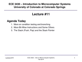
ECE 3430 – Introduction to Microcomputer Systems University of Colorado at Colorado Springs. Lecture #11 Agenda Today More on condition testing and branching More Bit-Wise Instructions and Some Others The Stack (Push, Pop) and the Stack Pointer. Condition Testing and Branching.

E N D
ECE 3430 – Introduction to Microcomputer SystemsUniversity of Colorado at Colorado Springs Lecture #11 Agenda Today • More on condition testing and branching • More Bit-Wise Instructions and Some Others • The Stack (Push, Pop) and the Stack Pointer ECE 3430 – Intro to Microcomputer Systems Fall 2014
Condition Testing and Branching In addition to CMP and TST instructions, you can use BIT to test certain bits. The source and destination are AND’ed together and the N, V, C, and Z flags updated in the status register. The destination is not modified! Test bits (accompanies CMP and TST instructions): BIT <src>,<dst> When JMP is out-of-range, use BR as an alternative. Unlimited, unconditional jump: BR <dst> ECE 3430 – Intro to Microcomputer Systems Fall 2014
More Instructions Decrement and Increment- Often used in loops to adjust “counters”- These add or subtract 1 or 2 from the destination (effective address) DEC <dst> ; x = x – 1 INC <dst> ; x = x + 1DECD <dst> ; x = x – 2 INCD <dst> ; x = x + 2 Ex) COUNT EQU 10FLASH EQU 0xC000 ORG FLASH mov #COUNT,R4 ; initialize loop counter LOOP: <loop body> dec R4 ; loop 10 times jne LOOP DONE: jmp DONE END ECE 3430 – Intro to Microcomputer Systems Fall 2014
More Instructions Arithmetic Shift- used to shift bits- note the characteristics of the end bits - preserves sign when shifting rightLEFT RLA <dst>Note: LSb is filled with ‘0’, MSb shift into carryRIGHT RRA <dst>Note: MSb is shifted into itself LSb is shifted into carry C N-1 0 0 N-1 0 C ECE 3430 – Intro to Microcomputer Systems Fall 2014
More Instructions Rotate- used to rotate bits- note the characteristics of the end bits, different from arithmetic shiftsLEFT RLC <dst>Note: full loop, MSb goes to carryRIGHT RRC <dst>Note: full loop, carry goes to MSb N-1 0 C N-1 0 C ECE 3430 – Intro to Microcomputer Systems Fall 2014
More Instructions Logical Shift- no explicit instructions in MSP430 to do this - to go left, use RLA - to go right, clear C flag (CLRC) and then use RRCLEFT Note: LSb is filled with ‘0’, MSb shift into carry RIGHT Note: 0 is shifted into MSb LSb is shifted into carry C N-1 0 0 0 N-1 0 C ECE 3430 – Intro to Microcomputer Systems Fall 2014
More Instructions ExampleWhat are the contents of R4 after each instruction?mov.b #10110110b, R4 R4Carry rra.b R4 1101 1011 0 rrc.b R4 0110 1101 1 rrc.b R4 1011 0110 1What CCR bits are altered and how?NZVC RLA * * * * RLC * * * * RRA * * 0 *RRC* * * * * = set to one or cleared to zero depending on run-time circumstances ECE 3430 – Intro to Microcomputer Systems Fall 2014
More Instructions 1’s and 2’s complement INV <dst> 1’s complement INV <dst> ADD #1, <dst> 2’s complement Examplemov.b #11110000b, R4 R4 = 00000000 11110000b inv.w R4 R4 = 11111111 00001111b add.w #1, R4 R4 = 11111111 00010000b ECE 3430 – Intro to Microcomputer Systems Fall 2014
More Instructions Clearing destination:CLR <dst> MOV #0,<dest> [zero out destination] Clearing C, N, Z flags: CLRC BIC #1,SR CLRN BIC #4,SR CLRZ BIC #2,SR Setting C, N, Z flags: SETC BIS #1,SR SETN BIS #4,SR SETZ BIS #2,SR Note the use of constant generators! ECE 3430 – Intro to Microcomputer Systems Fall 2014
More Instructions Swap bytes (little to big endian or vice versa): -> destination must be 16-bit SWPB <dst> Sign extend byte to word (8-bit to 16-bit signed cast): -> must be “room” for extension to 16-bits SXT <dst> No-operation (waste time, delay 1 cycle): NOP ECE 3430 – Intro to Microcomputer Systems Fall 2014
The Stack - This is just managed RAM. The “stack” can live anywhere in RAM. - This is a last in, first out (LIFO) data structure. - This is a first in, last out (FILO) data structure. - Items can only be added or removed from the top of the stack. - Conceptually like a stack of cafeteria trays or a PEZ dispenser. PUSH – inserting something onto the TOP of the STACK POP – removing something from the TOP of the STACKEx) PUSH 0x0011, 0x0022, 0x0033 POP, we will receive 0x0033, 0x0022, 0x0011 in that order TOP Last In This structure is useful because the order of data is inherently kept. We don’tneed to worry about setting up dedicated memory for each data item. This is also a necessary structure for subroutines to work. First In BOTTOM TOP 0x0033 0x0022 0x0011 ECE 3430 – Intro to Microcomputer Systems Fall 2014
The Stack The size of the arguments pushed to the stack can vary. In the MSP430, push operations can be 8 or 16-bit. Regardless, a full 16-bit value is allocated on the stack! In other words, the stack pointer is always even! All MSP430 pop operations deallocate 16-bits of data into the destination. ECE 3430 – Intro to Microcomputer Systems Fall 2014
The Stack What the stack really is:- A section of memory with an address pointer (stack pointer = SP in CPU).- The SP contains the address of the top element of the stack.- In the MSP430, the SP is pre-decremented as information is PUSHED.- In the MSP430, the SP is post-incremented as information is POPPED.- We define where to place the stack data structure (using mov instruction to initialize SP).- The stack is variable in size and only limited by RAM availability.- The standard is to place the STACK at the end of RAM (for our MSP430G2553, 0x0400). - The MSP430 provides instructions to manipulate the stack.- How do we initialize the stack? mov.w #0x0400,SP RAM Keep global variables close to the beginning of RAM 0x0200 : : 0x03FF Initialize stack at the end of RAM 0x0400 <no RAM here> ECE 3430 – Intro to Microcomputer Systems Fall 2014
The Stack Stack Overflow- If we push too much information onto the stack, it may start overriding data stored in pre-defined variables. - Since there is no operating system running on our MSP430, so you have to be the memory manager! MSP430 Stack Instructions PUSH (.b or .w) <src> always adds 16-bits (only touches 8 bits if .b) POP <dst> always removes 16-bits RAM Variables 0x0200 : : 0x03FF Stack creeps backwards through RAM as data is pushed onto it ECE 3430 – Intro to Microcomputer Systems Fall 2014
The Stack ExampleRemember that the SP points to the top word on the stack!mov.w #0x0400, SPmov.b #0xAA, R4mov.w #0xBBCC, R5push.b R4push.w R5pop R4 ; R4 = 0xBBCCpop R5 ; R5 = 0x??AANOTE: The data in RAM is not actually erased! 0x0400 SP xx 0x03FE0x03FF SP AA ?? 0x03FC 0x03FD0x03FE0x03FF SP CC BB AA ?? 0x03FE0x03FF SP AA ?? 0x0400 SP xx ECE 3430 – Intro to Microcomputer Systems Fall 2014
The Stack Dumb Example Program using the STACKSample port 1 10 times as fast as you can, then sum the result (in 2 loops)FLASH EQU 0xC000STACK EQU 0x0400RAM EQU 0x0200COUNT EQU 10 ORG RAMRESULT DS 2 ; allocate memory in RAM to hold result ORG FLASH ; start code at beginning of FLASH mov.w #STACK,SP ; initialize stack point to end of RAM mov.b #COUNT,R5 ; initialize loop counter clr.w RESULT ; initialize result to zero SAMPLE: mov.b &P1IN,R4 ; sample data on port 1 into R4 push R4 ; store the sample on the stack dec R5 ; decrement loop counter jne SAMPLE ; perform this task 10 times …continued ECE 3430 – Intro to Microcomputer Systems Fall 2014
The Stack mov.b #COUNT,R5 ; reinitialize the loop counter SUM: pop R4 ; bring in the information off the top of the stack add.w R4,RESULT ; continually sum this with RESULT dec R5 ; decrement loop counter jne SUM ; do this 10 timesDONE: jmp DONE END When the program finishes, the sum of the 10 samples is in RESULT.What is the value of SP after the “sample loop” completes?What is the value of SP after the “sum loop” completes? Did stack overflow occur? How could it have occurred? ECE 3430 – Intro to Microcomputer Systems Fall 2014
The Stack mov.b #COUNT,R5 ; reinitialize the loop counter SUM: pop R4 ; bring in the information off the top of the stack add.w R4,RESULT ; continually sum this with RESULT dec R5 ; decrement loop counter jne SUM ; do this 10 timesDONE: jmp DONE END When the program finishes, the sum of the 10 samples is in RESULT.What is the value of SP after the “sample loop” completes? 0x03ECWhat is the value of SP after the “sum loop” completes? 0x0400Did stack overflow occur? NOHow could it have occurred? Push more than 255 words on the stack, the 256th item would have overwritten RESULT ECE 3430 – Intro to Microcomputer Systems Fall 2014