Download
1 / 23
230 likes | 300 Views
This document discusses key issues and present design activities related to the LHD-type reactor FFHR, addressing compactness, high power density, low failure rate, and important design considerations. Topics include energy confinement enhancement, divotor systems, heating devices, maintenance methods, and more.

E N D
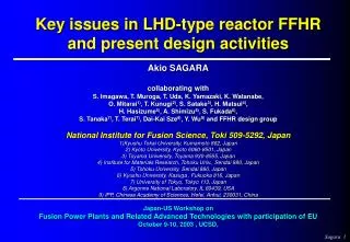
Key issues in LHD-type reactor FFHRand present design activitiesAkio SAGARAcollaborating withS. Imagawa, T. Muroga, T. Uda, K. Yamazaki, K. Watanabe, O. Mitarai1), T. Kunugi2), S. Satake3), H. Matsui4), H. Hasizume5), A. Shimizu6), S. Fukada6), S. Tanaka7), T. Terai7), Dai-Kai Sze8), Y. Wu9) and FFHR design groupNational Institute for Fusion Science, Toki 509-5292, Japan1)Kyushu Tokai University, Kumamoto 862, Japan2) Kyoto University, Kyoto 6060-8501, Japan3) Toyama University, Toyama 930-8555, Japan4) Institute for Materials Research, Tohoku Univ., Sendai 980, Japan5) Tohoku University, Sendai 980, Japan6) Kyushu University, Kasuga , Fukuoka 816, Japan7) University of Tokyo, Tokyo 113, Japan8) Argonne National Laboratory, IL 60439, USA9) IPP, Chinese Academy of Sciences, Hefei, Anhui, 230031, ChinaJapan-US Workshop onFusion Power Plants and Related Advanced Technologies with participation of EUOctober 9-10, 2003 , UCSD,
Issues on compactness FFHR-2 (1998 - ): LHD-type, 10m, 10T, 1.8%, 1GW A.Sagara, J.Plasma Fusion Research, 74(1998) pp.947-951.
We need High Power Density Need Low Failure Rate 燃料費 資本費 運転費 + + replacement cost C i O & M 年間経費 = COE = h 年間発電量 P Availability M fusion th 設備利用量 発電容量 Energy Need High Temp. Multiplication Energy Extraction After M. Abdou (in APEX)
26m 18.2m PF Coil Midplane Positioning ARIES-RS VECTOR-OPT ARIES-ST ITER 300 VECTOR-OPT VECTOR-A2 200 ARIES-RS Weight Power Dens. (kWF/ton) A-SSTR2 CREST VECTOR-ZERO DREAM SSTR 3GWth ARIES-I 100 ARIES-ST 1GWth ITER JT-60 FFHR-2 0 10000 20000 0 30000 Weight of ReactorMachine (ton) Importance of Weight Power Density By S.Nishio
Key issue Blanket space compact Main issues for Helical Demo 1. Enhancement of energy confinement 2. Data base at reduced g, outer shift,etc. 3. Reduction of heat load on the wall(a loss) 4. Divertor pumping systems (for a ash) 5. Fueling methods (to the center) 6. Heating devices (selection of method) 7. High performance blanket systems 8. Methods of maintenance & replacement 9. Advanced SC magnet systems 10. Structure materials and divertor materials 11. Reduction of construction cost 12. Reduction of COE
Outward shift of the magnetic axis by K.Watanabe [ref. Nuclear Fusion, 41(2001) 63.]
issue Enhancing inherent safety & Thermal efficiency issue Heat transfer & structure materials Molten-salt blanket with low MHD effect SC materials & Current density Expansion of blanket area High B design B^maxµ (IHJ)1/2 decrease issue issue Continuos winding helical coil MHD stability Reduction of magnetic force Simplification of supporting structure FFHR Design Concept & Optimization
Neutron wall loading is reduced toFn = 1.5MW/m2 (120dpa/10y) FFHR-2 A.Sagara et al., 17th IAEA _FTP-03 (1998) and ISFNT-5(1999, Rome) Qp~30, hth~38%, availability~0.8
=10year x 3E+13 n/m2s Should be reduced 5 orders from~ 5E+18 n/m2s in case of 1.5MW/m2 ( for En > 0.1 MeV at the first wall) Dose effect in SC coil under fast neutron irradiation H. Kodama et al., ICFRM-1, JNM 133&134 (1985) 819.
~3E+9 rad 1~2 order sever than SC Dose effect in insulator due to gamma-ray P.Komarek et al., ICFRM-3, JNM 155-157 (1988) 207.
● However, shielding efficiencyfor SC magnet should be improved more than one order. Self-cooled Tritium Breeding Blanket in FFHR ● Local TBR〜1.4. A.Sagara et al., Fusion Technol.,39 (2001) 753.
Conventional SC joint design ● SC joint is promising and innovative. (Ohmic heat on cryo. < a few % of Pf) T.Horiuchi et al., Fusion Technol. 8 (1985) 1654. • Re-mountable coils • using HTcS.C. joints • H.Hashizume et al., • J.Plasma Fusion Res. • SERIES 5 (2001) 532. Another approach using HTcSC for magnet coils Even the shielding efficiency is poor, ● temperature margin is wide, ● controllability becomes high at high T operation, (because specific heat ~ T3)
Reduction of the magnetic field to 6 T on axis • to provide more space for blanket and shield • to use NbTi in the helical windings. Increase of the FFHR2 configuration by 50% Jc reduced Modified FFHR-2 pressented in 12th Intenational Toki Conference (2002) IPP Garhing : H. Wobig, J. Kisslinger One way for optimization. But 3 times of the weight
Blanket in HSR 〜1.5m • He Cooled Li4SiO4 (KfK design) • He Cooled Pb-17Li (FZK design) • Water cooled Pb-17Li (ITER design)
Availability to use the center space in a large R helical rector
Reactor design activity in NIFS collaboration • on going • cf. NIFS annual repo.
Tohoku-NIFS Thermofluid loop for molten salt 40 kW (Fabricated by IHI Co., Ltd.) Max.20L/min @ 600°C ~ 0.1m3 @ 0.7MPa. Now HTS (simulant for Flibe) is used.
HERE 300 mm Flow 5mm 19.5mm Heat transfer enhancer at low flow rate … Packed-bed tube in TNT loop Fig.Re vs heat transfer characteristics (at 300 mm) Fig. Flow structure near wall (Result of 2D numerical simulation) About 3 times higher than turbulent heat transfer Fig.Pump frequency vs heat transfer coefficient (at 300 mm)
JUPITER-II project • Task 1-1-A • Task 1-1-B • Task 1-2-A • Task 3-1 MHD effects • Evaluation methodfor degradation of the insulator, induced pressure increase. • Proposing new methodto reduce the MHD pressure increase. • Clarification of feasibilityfor the liquid blanket system. 2003 NIFS Collaboration Program H.Hashizume (Tohoku Univ.) K.Muroga (NIFS) A.Sagara (NIFS) S.Tanaka (Tokyo Univ.) H.Horiike (Osaka Univ.) T.Kunugi (Kyoto Univ.) Other 8 reserchers
Velocity profiles (B=10[T]) By H. Hashizume [1] Flibe (b) Coated with Insulator (a) Without Insulator ( ) M-shape Flat-shape
[2] Lithium (a) Without Insulator (b) Coated with Insulator ( ) M-shape Flat-shape H.Hashizume et al., submitted to ISEM 2003: The 11th International Symposium on Applied Electromagnetics and Mechanics, Versailles, France
D-3He ignition is possible in the helical reactor with • R=14.47m, <ap>=2.585 m, Bo=6 T, and <b>~18 % • for the confinement enhancement factor of gHH = 2.4 • with the external heating power of PEXT= 300 MW • for D:3He fuel ratio of 2:1. • Parameter Requirements for D-3He Helical Reactors • O.Mitarai 1), • A. Sagara, S. Imagawa, Y.Tomita, K.Y.Watanabe and T.Watanabe 2) • 1) Kyushu Tokai University, 9-1-1 Toroku, Kumamoto, 862-8652 Japan, • 2) National Institute for Fusion Science, 322-6 Oroshi-cho, Toki, 509-5292 Japan • Submitted to ITC-13, Dec. 2003 @Toki, Japan
Summary Within present-day technology, medium-size designs are one way for helical demo-reactors. However, innovative concepts such as re-mountable coils using HTcS.C. joints are very attractive for compactness of LHD-type reactors. Design activities in NIFS collaborations are expanding intoThermofluid exp., MHD effects, D-3He, (& IFE).