Download
1 / 9
90 likes | 206 Views
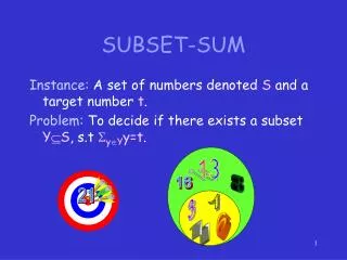
This paper compares various multicast receiver subsetting techniques proposed by Norman Finn and E. Eastlake. It evaluates the effectiveness of the four-address format and A-MSDU methods suggested by Finn, alongside Eastlake's approach that integrates lists of recipient addresses. The paper addresses the challenges associated with protocol requirements for mapping multicast addresses to specific receiver stations and the limitations of current A-MSDU implementations in adherence to IEEE standards. It aims to enhance frame transmission efficiency while managing receiver subsets in wireless communication.

E N D
Comparison of Receiver Subset Techniques Authors: • Date:2013-07-14 Norman Finn, Cisco Systems
Abstract • The subsetting techniques offered in documents 11-13/0141 (Finn) and 11-13/0526 (Eastlake) are compared. Norman Finn, Cisco Systems
Tagging format • Finn technique 1: Use four-address format. From AP, DA ≠ RA = multicast address specifying which stations are to receive the frame. To AP, SA ≠ TA = transmitting station. • Finn technique 2: Use A-MSDU. From AP, DA = RA = multicast address specifying which stations are to receive the frame. To AP, SA = TA = transmitting station. Inner (A-MSDU) DA and SA are the “real” DA and SA. • Eastlake technique: Use A-MSDU. Replace the first MSDU with a list of SAIDs that are (or are not) to receive the remaining MSDUs.
Common problems • Finn technique 1 and Finn technique 2: A protocol is required to distribute, to the stations, the mapping from multicast addresses to subsets of stations. While this mapping is in flux, extra transmissions of frames to unicast RAs are required. • Finn technique 2 and Eastlake technique: A frame carrying an A-MSDU is restricted to use a unicast RA. Also, an frame with an A-MSDU cannot be fragmented.
Protocol for distributing station maps • For the Finn solutions, the Receiver Address (whether in a 4-address frame or in a 3-address A-MSDU frame) indicates which stations are or are not to receive a frame transmitted by the AP. • Two subsets can be used without any additional protocol: • The broadcast address (all 1s) means, “this is for all stations.” It is used, for example, for DA group addresses that originated on the wired side of the AP. • A fixed address, perhaps 01-80-C2-01-xx-xx where “xx-xx” is the SAID of the one station that is notto receive the frame. It is used by the AP to reflect frames originating from station xx-xx. • Following the model of IEEE Std 802.1BR, the protocol would unicast to a station the list of RAs that it should (not) accept. When removing a station from an RA, the AP cannot use that RA until it receives the station’s ACK. When adding, the revised RA can be used immediately.
The unicast A-MSDU problem • According to IEEE Std 802.11-2012 Clause 9.11, Address 1 (RA=DA) must be an individual address. • In order to use A-MSDUs as suggested by either Eastlake or Finn technique #2, this restriction would have to be changed. • This change is necessary because the typical use case would be that the DA=RA=broadcast. • No individual unicast address would make sense, and using a fixed unicast address to mean, “everybody,” seems a gross misuse of 802 architecture. • This author does not know the reason for the restriction, and would welcome enlightenment.
The vector encoding problem • 11-13-0526 suggests replacing the first MSDU in the A-MSDU with a vector of recipients. • This author can suggest one method for doing this that makes no changes to the 802.11 headers. • In each A-MSDU, immediately following the source MAC address, we insert: • A new EtherType meaning, “List of receivers’ SAIDs follows”. • At least a few bits for revision, and something to indicate whether this is a list of receivers or a list of non-receivers. • List(s) of SAIDs, bit vectors of SAIDs, ranges of SAIDs, etc., as we choose to encode them. • By inserting the list using a tag, we can avoid any confusion with existing uses of A-MSDUs.
Frame size • In Finn proposal 1, each frame is 6 bytes longer than an existing 3-address frame, because it carries all 4 addresses. • In Finn proposal 2, each frame is 12 bytes longer than an existing frame, which is required by the A-MSDU encoding. The 12 bytes are the Source and Destination addresses in the A-MSDU. • In the Eastlake proposal, assuming the SAID encoding described, above, each frame is longer by 14 bytes (the two addresses and the new EtherType), plus the length of the list of SAIDs, which is arbitrary. • Note that no EtherType or list is needed for the “all but one” case, as that can be handled by the “all but one” Receiver Address. Norman Finn, Cisco Systems
Summary Norman Finn, Cisco Systems
![Data Modeling [Comparison of data modeling techniques ]](https://cdn0.slideserve.com/205866/data-modeling-comparison-of-data-modeling-techniques-dt.jpg)


![Data Modeling [Comparison of data modeling techniques ]](https://cdn3.slideserve.com/6795343/data-modeling-comparison-of-data-modeling-techniques-dt.jpg)