Download
1 / 18
180 likes | 349 Views
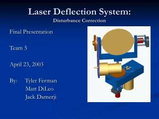
Disturbance Correction. Final Design Review Team 5 February 25, 2003 By: Tyler Ferman Matt DiLeo Jack Damerji. Laser Deflection System. Project Overview User supplies changing input. Goal is to compensate for measured input disturbance.

E N D
Disturbance Correction Final Design Review Team 5 February 25, 2003 By: Tyler Ferman Matt DiLeo Jack Damerji
Laser Deflection System • Project Overview • User supplies changing input. • Goal is to compensate for measured input disturbance. • Controller angles mirror to performs disturbance correction. • Objectives • Develop accurate controller in order to keep a laser communication link. • Develop controller to correct for all disturbance.
Approach • Input • Measure the laser pen pan/tilt angles. • Measure the mirror pan/tilt angles. • Controller • Determination of desired mirror pan/tilt angles. • Develop controller to achieve performance specifications. • Output • Specified target (dot on wall)
Specifications Cont. • Input range of motion: 43o • Mirror: 5’’ dia @ 55g (+ 45g mount) • Output Range of motion: 26o • Controller Speed: >6rad/s • Overshoot Error: < 1% • Target: +-0.4” • Encoder Gearing: 1:4 (4X accuracy)
Math Model (Angle Calc.) Pan/Tilt & Mirror Design Motor & Gear Selection Mass & Inertia Calc. Simulation & Controller Design 2/19 System Analysis Input Pan/Tilt Considerations Order parts 2/26 Building Input Pan/Tilt Build Control Pan/Tilt Input Pan/Tilt &DSP DSP Control of Pan/Tilt Input Testing Testing and Fine Tuning 4/1 Develop Full Interaction 4/9 Testing, Tolerance Analysis & Fine Tuning
Math Model (Angle calc.) • Approach: • Direct: • Solve by equating desired reflected unit vector with received reflected unit vector • Solve using parametric equations • Indirect: • Solve using Coordinate Transformations • Solve using fminsearch & foreword equation Find foreword Equation (Maple) Solve For Mirror Angles (Maple) Create Math Model (MATLAB) Find foreword Equation (Maple) Educated Angles Guess (MATLAB) Iterate Until Guess Converges
Math Model (Angle Calc.) Pan/Tilt & Mirror Design Motor & Gear Selection Mass & Inertia Calc. Simulation & Controller Design 2/19 System Analysis Input Pan/Tilt Considerations Order parts 2/26 Building Input Pan/Tilt Build Control Pan/Tilt Input Pan/Tilt &DSP DSP Control of Pan/Tilt Input Testing Testing and Fine Tuning 4/1 Develop Full Interaction 4/9 Testing, Tolerance Analysis & Fine Tuning
Motor & Gears Selection • Center Of Gravity and Inertia were obtained from Solid Work Models • Simulate a number of motors Examples: Tested number of GM8000 series Needed more: Torque & Speed Motor Chosen:Pittman GM9234S016Gear Ratio: 4:1
Math Model (Angle Calc.) Pan/Tilt & Mirror Design Motor & Gear Selection Mass & Inertia Calc. Simulation & Controller Design 2/19 System Analysis Input Pan/Tilt Considerations Order parts 2/26 Building Input Pan/Tilt Build Control Pan/Tilt Input Pan/Tilt &DSP DSP Control of Pan/Tilt Input Testing Testing and Fine Tuning 4/1 Develop Full Interaction 4/9 Testing, Tolerance Analysis & Fine Tuning
Input Considerations • Input trajectory accuracy is critical • S1 Optical Shaft Encoder • 1024 CPR 3600/1024 = .350 per tick • S2 Optical Shaft Encoder • 2048 CPR 3600/2048 = .1760 per tick • Geared S1 Encoder • 1024*4 CPR 3600/4096 = .090 per tick
Error Induced >> [r,u,p]=find_reflected([0,-2.5,6], [0,.178543307087,-1], [0,0,1]); >> [x,y,z]=vec_plane_int(p,u,[0,0,-1],[0,0,36]) x = 0 y = 4.9988 z = 36 >> [r2,u2,p2]=find_reflected([0,-2.5,6], [0,.180344836659,-1], [0,0,1]); >> [x2,y2,z2]=vec_plane_int(p2,u2,[0,0,-1],[0,0,36]) x2 = 0 y2 = 5.0745 z2 = 36 • Output error due to input measurement accuracy • 0.10 input error ~0.0745’’ output error
Ordering Parts • Project Budget • List of Parts • List of Materials • Machine shop service
List of Materials Machine Shop Service
Project Budget Summary Total Cost
Θin1 DSP I/O State Estimator Trajectory Calculator Θin2 Desired States (Θ1, Θ2, Θ1dot, Θ2dot) Mirror Position Calculator Angle Saturation Controller Torque Θ1 Estimated States (Θ1, Θ2, Θ1dot, Θ2dot) State Estimator Θ2 Torque Motor Control Voltage for Motors
Math Model (Angle Calc.) Pan/Tilt & Mirror Design Motor & Gear Selection Mass & Inertia Calc. Simulation & Controller Design 2/19 System Analysis Input Pan/Tilt Considerations Order parts 2/26 Building Input Pan/Tilt Build Control Pan/Tilt Input Pan/Tilt &DSP DSP Control of Pan/Tilt Input Testing Testing and Fine Tuning 4/1 Develop Full Interaction 4/9 Testing, Tolerance Analysis & Fine Tuning