UV-Vis Absorption Spectroscopy
UV-Vis Absorption Spectroscopy. Lecture 23. Instrumental Noise as a Function in Transmittance.

UV-Vis Absorption Spectroscopy
E N D
Presentation Transcript
UV-Vis Absorption Spectroscopy Lecture 23
Therefore, an absorbance between 0.2-0.7 may be advantageous in terms of a lower uncertainty in concentration measurements. At higher or lower absorbances, an increase in uncertainty is encountered. It is therefore advised that the test solution be in the concentration range which gives an absorbance value in the range from 0.2-0.7 for best precision. However, it should also be remembered that we ended up with this conclusion provided that sT is constant. Unfortunately, sT is not always constant which complicates the conclusions above.
EFFECT OF bandwidth Effect of bandwidth on spectral detail for a sample of benzene vapor. Note that as the spectral bandwidth increases, the fine structure in the spectrum is lost. At a bandwidth of 10 nm, only a broad absorption band is observed.
Effect of slit width (spectral bandwidth) on peak heights. Here, the sample was s solution of praseodymium chloride. Note that as the spectral bandwidth decreases by decreasing the slit width from 1.0 mm to 0.1 mm, the peak heights increase.
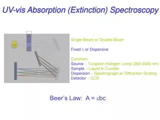
Effect of Scattered Radiation at Wavelength Extremes of an Instrument Wavelength extremes of an instrument are dependent on type of source, detector and optical components used in the manufacture of the instrument. Outside the working range of the instrument, it is not possible to use it for accurate determinations. However, the extremes of the instrument are very close to the region of invalid instrumental performance and would thus be not very accurate. An example may be a visible photometer which, in principle, can be used in the range from 340-780 nm. It may be obvious that glass windows, cells and prism will start to absorb significantly below 380 nm and thus a decrease in the incident radiant power is significant.
What defines the instrumental wavelength extremes? Two Factors: • Source • Detector Measurements at wavelength extremes should be avoided since errors are very possible due to: • Source limitations • Detector limitations • Sample cell limitations • Scattered radiation
B: UV-VIS spectrophotometer A: VIS spectrophotometer EFFECT OF SCATTERED RADIATION Spectrum of cerium (IV) obtained with a spectrophotometer having glass optics (A) and quartz optics (B). The false peak in A arises from transmission of stray radiation of longer wavelengths.
The output from the source at the low wavelength range is minimal. Also, the detector has best sensitivities around 550 nm which means that away up and down this value, the sensitivity significantly decrease. However, scattered radiation, and stray radiation in general, will reach the detector without passing through these surfaces as well as these radiation are constituted from wavelengths for which the detector is highly sensitive. In some cases, stray and scattered radiation reaching the detector can be far more intense than the monochromatic beam from the source. False peaks may appear in such cases and one should be aware of this cause of such peaks.