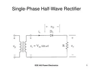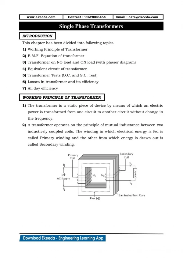
Single Phase, Full wave, R load
v s. ω t. α. α. Single Phase, Full wave, R load. T 1. I 1. i G2. i G2. I L. i G1. i G1. i G1. i G1. I 2. i G2. +. T 2. V S. R. V L. _. V L. v S = V m sin ( ω t ). π. ω t. V Lrms = V m √ 1/ π ( α ∫ π sin 2 ( ω t) d( ω t ))

Single Phase, Full wave, R load
E N D
Presentation Transcript
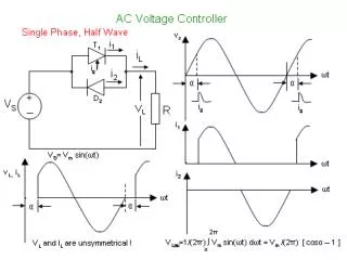
vs ωt α α Single Phase, Full wave, R load T1 I1 iG2 iG2 IL iG1 iG1 iG1 iG1 I2 iG2 + T2 VS R VL _ VL vS= Vm sin ( ωt ) π ωt VLrms= Vm √ 1/ π (α∫πsin2 (ωt) d(ωt )) = Vm √ 1/(2π) (α∫π(1-cos(2 ωt) d(ωt )) = Vm √ 1/(2π) × (π – α +½ sin(2α))
Isolation of the Gate T1 T2 D1 D3 T D2 D1 D4 D2
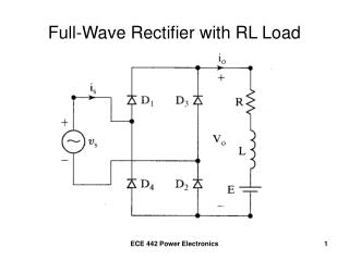
ωt VS Single Phase, Full wave, R-L load T1 I1 IL iG2 iG2 iG1 iG1 iG1 iG1 R I2 T2 iG2 + VS VL _ L i1 vS(ωt) = Vm sin(ωt) i2 i1(ωt) = Vm / │Z │ sin(ωt – φ) + A exp-[(ωt-α)/ωζ] for α ≤ ωt ≤ α+γ i1(α) = 0 A = - Vm / │Z │ sin(α – φ) i1(ωt) = Vm / │Z │ sin(ωt – φ) - sin(α – φ) exp-[(ωt-α)/ωζ] for α ≤ ωt ≤ α+γ i1(ωt) = 0 for α+γ ≤ ωt ≤ 2π+α ωt ωt Where │Z │= √(R2+ω2L2) φ= tan-1(ωL/R) ζ = L/R
ωt ωt iL VLrms= √ Vm2 / πα∫(α+γ) sin2(ωt) d(ωt) = Vm √ 1/(2π) α∫(α+γ) [1-cos(2 ωt)] d(ωt) = Vm √ 1/(2π) [ωt - ½ sin(2ωt)]αα+γ = Vm √ 1/(2π) [ γ - ½ sin(2α+2γ) + ½ sin(2α)] Note that we need that α > φ so that γ < π ie T1stops conducting before firing T2 vL When α = π VLrms= Vm / √2 ( no control) φ Calculation of γ γ α i1(α+ γ) = 0 sin(α+γ– φ) - sin(α – φ) exp-[(γ)/ωζ] = 0 Transcendental equation
The relation between γ and α 1- Pure R load Φ= 0 i1 = Vm / R × sin(ωt) γ = π - α γ 2π R-L load 2- pure L load Φ = 90o i1 = Vm / (ωL) × ( - cos(ωt) + cos α ) I1 = 0 @ ωt = α + γ cos(α + γ) = cos α α + γ = 2π – α γ = 2π – 2α γ = π - α π pure L load pure R load π/2 π α
3-phase ac Voltage Controller vcn vbn vanL van T1 R α1=0 α3=0 α5=0 van T4 ωt T3 R α4=0 α2=0 n n α6=0 vbn Control ranges 0 ≤ α < 60o 60o ≤ α < 90o 90o ≤ α < 150o T6 T5 R vcn T2
vanL van vbn vcn ½Vac For 0o ≤ ωt ≤ α Assume that T5 and T6 are conducting Since neither T1 or T4 is conducting, then vanLis zero. ½Vab ωt For α ≤ ωt ≤ 60o T1 conducts in addition to T5 and T6. Note that van and vcn are +ve, while vbn is –ve. This means that the load is connected to the 3 supply lines. vanL= van in this interval. α 60o (α= 30o) For 60o ≤ ωt ≤ 60o+ α @ 60o T5 ceases to conduct since the load is pure resistive. In this interval only T6 and T1 conduct. This means that vanL= ½vabin this interval. For 120o ≤ ωt ≤ 120o+ α @ 120o T6 ceases to conduct since the load is pure resistive. In this interval only T1 and T2 conduct. This means that vanL= ½vac in this interval. For 60o+α ≤ ωt ≤ 120o @ 60o+α T2 conducts. In this interval T6, T1 in addition to T2 are conducting. van is +ve, while vdn and vcn are –ve. This means that the load is connected to the 3 supply lines. vanL = vanin this interval. For 120o+α ≤ ωt ≤ 180o @ 120o+α T3 conducts. In this interval T1, T2 in addition to T3 are conducting. Van and vbn are +ve, while vcn is –ve. This means that the load is connected to the 3 supply lines. vanL = vanin this interval.
vanL van vbn vcn ½Vac For 180o ≤ ωt ≤ 180o+α T1 ceasesto conduct while T2 and T3 are conducting. Since neither T1 or T4 is conducting, then vanLis zero. ½Vab ωt For 180o+α ≤ ωt ≤ 240o T4 conducts in addition to T2and T3. Note that vbn is +ve, while van and vcn are –ve. This means that the load is connected to the 3 supply lines. vanL= van in this interval. α 60o (α= 30o) For 240o ≤ ωt ≤ 240o+ α @ 240o T2 ceases to conduct since the load is pure resistive. In this interval only T3 and T4 conduct. Since vbn is +ve while van and vcn are –ve, vanL= ½vab which is –ve in this interval. For 300o ≤ ωt ≤ 300o+ α @ 120o T3 ceases to conduct since the load is pure resistive. In this interval only T4 and T5 conduct. Van is -ve, while vcn is +ve. This means that vanL= ½vac in this interval, and is -ve. For 240o+α ≤ ωt ≤ 300o @ 240o+α T5 conducts. In this interval T3, T4 in addition to T5 are conducting. van is -ve, while vbn and vcn are +ve. This means that the load is connected to the 3 supply lines. vanL = vanin this interval. For 300o+α ≤ ωt ≤ 360o @ 300o+α T6 conducts. In this interval T4, T5 in addition to T6 are conducting. van and vbn are -ve, while vcn is +ve. This means that the load is connected to the 3 supply lines. vanL = van in this interval. At ωt=360o, T4 ceases to conduct, this means that T5 and T6 remain conducting. This coincides with oue assumption during the interval 0o ≤ ωt < α
For 0 ≤ α ≤ 60o VLrms = Vm√{1/(2π){ π/3 - ½ sin120o – α + ½ sin(2α) + π + 6α – 3 sin(180o+2α) – π + 3 sin(180o) + 2π/3 - ½ sin(240o) – π/3 – α + ½ sin(120o+2α) + π - ½ sin(360o) - 2π/3 – α + ½ sin(240o+2α) } } = Vm√{1/(2π) { - π - √3 /4 + √3 /4 + 3α + ½ sin(2α) + ½ sin(2α+120o) + ½ sin(2α-120o) } } = Vm√{1/(2π) { - π + 3α + ½ sin(2α) + ½ [sin(2α) cos(120o) + cos(2α) sin(120o) + sin(2α) cos(120o) - cos(2α) sin(240o)] } } = Vm√{1/(2π) { - π + 3α + ½ sin(2α) + sin(2α) cos(120o) } } = Vm√{1/(2π) { - π + 3α + ½ sin(2α) - ½ sin(2α) }
C G E Transistor Switches • Very small reverse voltage capability • Fully controlled BJT (Bipolar Junction Transistor) Power MOSFET Metal Oxide Semiconductor Field Effect Transistor IGBT Insulated Gate Bipolar Transistor D C N channel MOSFET G B NPN S E voltage controlled current controlled
DC to DC Converters ( Choppers) Chopper constant voltage dc source variable voltage dc load PWM control