Download
1 / 11
170 likes | 738 Views
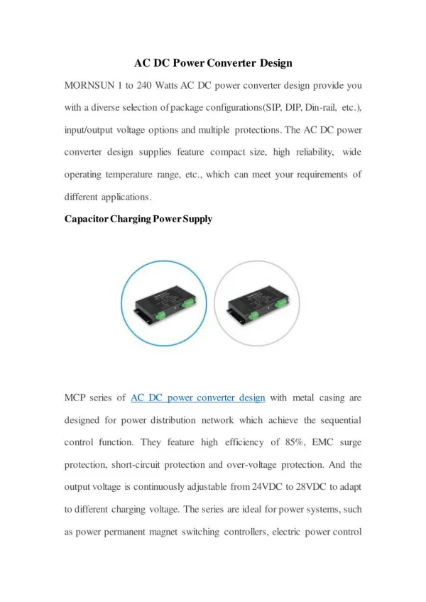
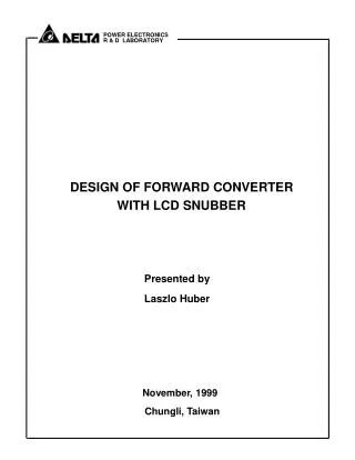
DESIGN OF FORWARD CONVERTER WITH LCD SNUBBER. Presented by Laszlo Huber. November, 1999. Chungli, Taiwan. EXAMPLE DPS-200PP-76. 1. SPECIFICATIONS Line voltage: 90-265 V, 47-63 Hz Outputs: 5 V / 1.5-20 A 12 V / 0.2-8 A 3.3 V / 0-20 A -5 V / 0-0.3 A -12V / 0-0.4 A

E N D
DESIGN OF FORWARD CONVERTER WITH LCD SNUBBER Presented by Laszlo Huber November, 1999 Chungli, Taiwan
EXAMPLE DPS-200PP-76 • 1. SPECIFICATIONS • Line voltage: 90-265 V, 47-63 Hz • Outputs: 5 V / 1.5-20 A • 12 V / 0.2-8 A • 3.3 V / 0-20 A • -5 V / 0-0.3 A • -12V / 0-0.4 A • 5 Vaux / 5-720 mA • Pomax = 200 W (combined 5V/3.3V Pomax = 120 W) • Pomin = 9.9 W (~ 5%) • Hold-up time: 10 ms • 2. TOPOLOGY • Multi-output forward converter with non-dissipative (LCD) snubber and voltage-doubler rectifier (w/o PFC) • 3. MAJOR DESIGN COMPONENTS • Bulk capacitors CB1,2 • Primary-side switch Q • Secondary-side diodes • Forward Transformer T • Forward inductors
4. BULK CAPACITORS CB1,2 At low-line range With
5. VBmin WITH HOLD-UP TIME Const. power load Forward converter should be designed for bulk-voltage range:
6. FORWARD CONVERTER TRANSFER FUNCTION Derivation of forward-converter transfer function from forward-inductor flux-balance (CCM):
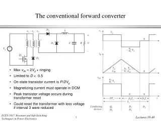
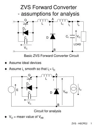
7. COMPARISON OF DIFFERENT RESET TECHNIQUES FOR FORWARD TRANSFORMER • Reset winding • RCD clamp • Active clamp • LCD snubber 7.1 FORWARD CONVERTER WITH RESET WINDING Transformer flux balance: Maximum switch voltage: Usually:
7.2 FORWARD CONVERTER WITH RCD CLAMP Clamp voltage Vcl f (VB) ! Goal: 600-V MOSFET From transformer flux balance: Turns ratio (@ 5V output) Sec-side diodes:
7.3 FORWARD CONVERTER WITH ACTIVE CLAMP Clamp voltage Goal: 600- V MOSFET From transformer flux balance: Design approach:
Derivation of Dmax + Dmin = 1 (1) (2) (3) Substitute Vclmax from (1) and Vclmin from (2) into (3): (4) (5) (6) From the forward-converter transfer function (7) Combining (6) and (7):
Turns ratio (@ 5V output) Sec-side diodes: 25 - 35 V Schottky Diode Advantages of active-clamp reset: — larger N lower current stress on prim.-side lower voltage stress on sec.-side — transformer operates in I and III quadrant From Faraday’s Law: smaller core ( Ac ) — ZVS (Zero-voltage-svitching) efficiency higher switching frequency — lower EM I