Download
1 / 15
150 likes | 305 Views
Expected damage on TCTA collimator during HRMT09-LCOL experiment in HiRadMat facility Collimation Working Group 30.7.2012 F. Carra A. Bertarelli, A. Dallocchio, L. Lari, N. Mariani. Outlook. Scope of the study performed FEA 3D model Damage classification Accident simulation results Test 1

E N D
Expected damage on TCTA collimator during HRMT09-LCOL experiment in HiRadMat facilityCollimation Working Group30.7.2012F. CarraA. Bertarelli, A. Dallocchio, L. Lari, N. Mariani Federico Carra – EN-MME
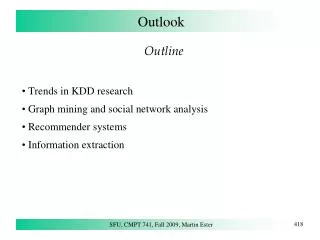
Outlook • Scope of the study performed • FEA 3D model • Damage classification • Accident simulation results • Test 1 • Test 2 • Test 3 • Conclusions Federico Carra – EN-MME
Scope of the studypresented • Three different testson the TCTA will be performed in HiRadMat facility : • Test 1: to reproduce LHC asynchronous dump (single bunch setup, 1 bunch at 7 TeV energy impacting tungsten jaw) • Test 2: to assess the threshold damage on the collimator, in terms of beam energy and intensity (damage not imposing collimator replacement) • Test 3: to reproduce a destructive scenario and benchmark simulations (“Limits for Beam-InducedDamage: Reckless or tooCautious?“,A. Bertarelli et al. , Chamonix 2011) How many SPS bunches (and at which intensity) are necessary to reproduce the 3 different scenarios, identified for the LHC? FLUKA simulations – L. Lari: Equivalence of the energy peak + Autodyn FEA – F. Carra: Equivalence of the damage produced on the jaw Federico Carra – EN-MME
Equivalentdamage: LHC vs. SPS • Preliminary analyses – FLUKA (L. Lari) • Equivalence of the energy peak • Equivalence of the maximum temperature (considering adiabatic conditions, constant specific heat) • Input for successive Autodyn FEA • Autodyn FEA • Equivalence of the damage produced on the jaw • Shockwave is propagating during the time between two successive bunches → pressure waves are not linearly superposing! Federico Carra – EN-MME
FEA: 3D Model +/-10 mm through 5th axis Stiffener (Glidcopmodeled as OFE-Cu) Water Screw (x40) (Stainless Steel) Block Support (OFE-Copper) Cooling Pipes (Cu(89%)-Ni(10%)-Fe(1%) modeled as OFE-Cu) Jaw block (x5) (W(95%)-Ni(3.5%)-Cu(1.5%)partly modelled as pure W) Federico Carra – EN-MME
Damageclassification Three different damage scenarios, with increasing severity, were identified: Jaw Damaged Area (red) Level 1 : H ≤ 8 mmLevel 2: H > 8 mm • Level 1 (Collimator need not be replaced). Limited jaw damage, an intact spare surface can be found relying on the 5th axis movement (+/- 10 mm). (Provided this movement is possible). Permanent jaw deformation is limited. • Level 2 (Collimator must be replaced). Damage to collimator jaw is incompatible with 5th axis travel (H > 8 mm). Other components may also be damaged (e.g. Screws). • Level 3 (Long down time of the LHC). Catastrophic damage to collimator leading to water leakage into beam vacuum (pipe crushing, tank water circuit drilling ...) Federico Carra – EN-MME
Test 1: beamparameters • SPS (HiRadMat) scenario • 440 GeV • X bunches • 1,5E11 p/b • σ = 0.5x0.5 mm2 • Impact parameter: • x = 2 mm • y = 10 mm • Bunch spacing: 50 ns • LHC scenario • 7 TeV • 1 bunch • 1,5E11 p/b • σ = 0.5x0.5 mm2 • Impact parameter (test): • x = 2 mm • y = 10 mm ??? • Preliminary estimation with FLUKA: 20 SPS bunches to have an equivalent energy peak Energy peak in the axial coordinate, courtesy of L. Lari Federico Carra – EN-MME
Test 1: expecteddamageprovoked by 1 LHC bunch, 7 TeV • Tungsten damaged zone ~ 9 mm + plastic deformation of copper beam • Maximum pl. strain on pipes ~ 2.1% Federico Carra – EN-MME 1 bunch, 7 TeV: cooling pipes
Test 1: equivalent SPS bunches • 20 SPS bunches are necessary to provoke the same damage which is expected for 1 LHC bunch on the tungsten jaw • For an LHC equivalent damage on the cooling pipes, 30 SPS bunches are necessary! • Scratch on the W jawvs.Damage on cooling pipes: which one to use as a reference? Federico Carra – EN-MME
Test 2: beamparameters • SPS (HiRadMat) scenario • 440 GeV • X bunches → X = max. n. SPS bunches for which 80% of W melting temperature is not exceeded (S. Redaelli) • 1,5E11 p/b • σ = 0.5x0.5 mm2 • Impact parameter: • x = 2 mm • y = 10 mm • Bunch spacing: 50 ns W grains Metallic matrix Inermet: Cu/Ni Densimet: Fe/Ni Inermet microstructure Federico Carra – EN-MME
Test 2: results • 6 bunches to stay below 80% of W melting temperature (unavoidable melting of Cu/Ni phase) • No plastic strain of the tungsten active surface • Scenario equivalent to 1 LHC bunch, 7 TeV, 4.5e10 p 6 bunches, 440 GeV – Temperature Federico Carra – EN-MME
Test 3: beamparameters • SPS (HiRadMat) scenario • 440 GeV • X bunches • 1,5E11 p/b • σ = 0.5x0.5 mm2 • Impact parameter: • x = 2 mm • y = 10 mm • Bunch spacing: 50 ns • LHC scenario • 5 TeV • 4 bunches • 1,3E11 p/b • σ = 0.5x0.5 mm2 • Impact parameter (test): • x = 2 mm • y = 10 mm • Bunch spacing: 25 ns ??? • Preliminary estimation with FLUKA: 50 SPS bunches to have an equivalent energy peak Energy peak in the axial coordinate, courtesy of L. Lari Federico Carra – EN-MME
Test 3: expecteddamageprovoked by 4 LHC bunches, 5 TeV • Coarser mesh to reduce calculation times • Change of density between each of the last bunches is introducing an error > 10% Calculation will be refined in the next weeks • Considerable vertical deformation of the copper beam • Extensive damage on the tungsten jaw • Plastic strain on cooling pipes ~ 10%! 4 bunches, 5 TeV: Vertical Displacement Federico Carra – EN-MME
Test 3: equivalent SPS bunches • ~ 65 SPS bunches are necessary to provoke the same damage which is expected for 4 LHC bunch (5 TeV) on the tungsten jaw • In the HiRadMat facility, an equivalent damage provoked on the cooling pipes by 4 LHC bunches (5 TeV) is not reproducible! (decreasing beam σ would have very limited effect ) Federico Carra – EN-MME
Conclusions • Simulations were performed with FLUKA and Autodyn in order to evaluate the correct beam parameters for HRMT09 experience. • Test 1: 20 bunches proposed for an equivalent damage on W jaw; 30 bunches to have the same pipes plastic deformation. What part of the jaw to be taken as a reference? • Test 2: 6 bunches are proposed: Tmax < 0.8Tmelt(W), no plastic deformation of active jaw surface. Total beam intensity: 9e11 protons. • Test 3: 65 bunches are proposed: damage on W jaw is equivalent to the destructive case that should be reproduced. With current HiRadMat parameters, high plastic strain levels on cooling pipes cannot be reached. Federico Carra – EN-MME