Download
1 / 42
450 likes | 704 Views
Novel dual- V th independent-gate FinFET circuits. Masoud Rostami and Kartik Mohanram Department of Electrical and Computer Engineering Rice University, Houston, TX. Outline. Introduction and motivation Background Dual- V th independent-gate FinFETs Logic design Simulation results

E N D
Novel dual-Vth independent-gateFinFET circuits Masoud Rostami and Kartik Mohanram Department of Electrical and Computer Engineering Rice University, Houston, TX
Outline Introduction and motivation Background Dual-Vth independent-gate FinFETs Logic design Simulation results Conclusions and future directions
Introduction Technology scaling Process variations Leakage power Short channel effects Planar double-gate FETs and FinFETs Compatibility with planar CMOS Scalability Suppression of short channel effects Low parametric variations High Ion/Ioff
Motivation • Conventional FinFETs • Tied-gate devices • Independent-gate FinFETs • Removing top oxide • Electrically isolated, electrostatically coupled gates • Muttreja, Agarwal, and Jha, ICCD, 2007 • Caciki and Roy, IEEE TED, 2007 • Tawfik and Kursun, Microelectronics Journal, 2009
Motivation • Conventional FinFETs • Tied-gate devices • Independent-gate FinFETs • Low-power logic gates • Disabled, reverse-biased back-gate • Independent-gate logic gates • Merge parallel transistors, compact logic
Motivation • Merge series transistors? • Dual-Vth independent-gate FinFETs • Device design considerations
Motivation • Merge series transistors? • Dual-Vth independent-gate FinFETs • Device design considerations • Independent-gate dual-Vth FinFETs • Logic design opportunities • Compact logic gates • New family of logic gates • Delay+power+area evaluation
Background • FinFET • Cross-sectional view Front Gate tox Drain n+ Channel (undoped) Source n+ tsi L Back Gate Underlap
Background 9 • FinFET models • University of Florida double-gate (UFDG) • Physics-based, good agreement with manufactured devices • Fin height, silicon thickness, S/D doping, underlap, gate electrode work-function • Predictive technology model (PTM) • Modeled as two parallel coupled SOI devices
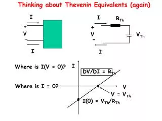
Background • Finfet threshold voltage VT • Φms and Cox tuning • Independent-gate FinFETs • Electrically isolated, electrostatically coupled • Vth-dependence model [Colinge 2008] • Vth-front = Vth-front0– δ (Vgbs – Vth-back) if Vgbs < Vth-back • Vth-front = Vth-front0 in all other cases • Substrate-like effect in planar CMOS 10
Dual-Vth FinFETs • Φms tuning • Two additional mask steps • Cox tuning through tox • Asymmetric oxides [Masahara, IEEE EDL 2007] • Device design using UFDG model
Dual-Vth FinFETs VDS= 1V IDS(A) VGS(V)
Dual-Vth FinFETs • TCAD simulations (2D Sentaurus) • Same device geometry 2D Sentaurus UFDG
Dual-Vth FinFETs UFDG 2D Sentaurus
Dual-Vth FinFETs • Good Vth separation • Good noise margin (approx. 0.5Vdd) • Leakage current in high-Vth device • pA for low-Vth devices • nA for high-Vth devices in disabled-gate mode • Comparable to 32nm CMOS
Dual-Vth logic gates • Rules for pull-down and pull-up network: • Parallel structure ↔ series structure • “Weak” AND-like high-Vth transistor ↔ “strong” OR-like low-Vth transistor 16
Novel dual-Vth logic gates • Novel logic gates • Independent back-gate as independent input • n-input gate with n, n+1, …, 2n inputs • Example f = (a + b)(c + d) • n = 2, 12 unique combinations • Some competitive, some not • Exponential in n • Occupancy problem • Series-parallel graphs • Functionally equivalent, electrically different gates
Results • Technology libraries for n = 3 • Basic library • Traditional INV, NAND, NOR, AOI, OAI • Previous work library = Basic library + • Compact gate with parallel transistors merged • Low power gates with disabled back-gate • Merged series = Previous work library + • Dual-Vth logic gates, with series transistors merged as appropriate • Complete library = Merged series library + • Novel dual-Vth logic gates
Results • ISCAS and OpenSPARC circuits • Area (no. of fins), delay, total power • Improvements: Basic, Previous work, Merged series • Area savings: 27%, 23%, 12% • Delay improvement: 7%, 7%, 1% • Total power: 24%, 21%, 15% • Static power • 10-100X higher, but net contribution negligible • Dynamic power • Dominates • Improvements with proposed complete library significant
Conclusions • Dual-Vth FinFET design • Gate work-function • Oxide thickness • UFDG-based search and 2D TCAD validation • Compact merged series-parallel logic gates • Novel dual-Vth logic gates • New opportunities for FinFET-based design • Leakage power control • Underlap as a design parameter
Double gate devices • Reduction in relative strength of gate • Two gates bring more electrostatic stability • Double gate devices have: • Less DIBL, GIDL and leakage power • Better Ion/Ioff • Better subthreshold slope • Fabrication issues (alignment, etc)
FinFET • FinFETs are folded channel MOSFETs • Easy manufacturingprocess • Narrow vertical fin(s) stick up from the surface [1] D. Hisamoto, et al, “FinFET—A Self-Aligned Double-Gate MOSFET Scalable to 20nm”, IEEE Tran on Electron Devices [1]
FinFET cross view • Can you see the underlap? • Channel engineering unfeasible • Different strength for each gates is possible by tuning: • Work–function • Oxide thickness Front Gate Tox Source n+ Channel-Undoped Drain p+ Tsi Length Back Gate
Outline • Introduction and motivation • Device characteristics • Circuit innovation with FinFET and results • Future directions and conclusion
I-V curves (current vs. drain voltage) • PMOS • NMOS Off-current On-Current Ids Ids Vds Vds
Backgate and discrete “width” • Disabling the backgate: • An order of magnitude less on-current • Less static leakage • Suitable for off-critical paths • The height cannot be changed across chip • Stronger devices by adding parallel fins [1] • Gate sizing will be a discrete problem • W = n.Hfinn=1,2,… [1] J. P. Colinge, “FinFET and other multi-gate transistors”, chapter 1 and 7, Springer, 08
DC properties • No dopant in channel: • No random dopant fluctuations • No Coulomb scattering => Higher mobility • Higher concentration of traps • Higher flicker noise and noise figure • Due to 3D structure • Much higher heat transmission resistance • Danger of thermal runaway [1] • Performance degrades less in alleviated temperatures [1] J. H. Choi, et al, “The Effect of Process Variation on Device Temperature in FinFET circuits”, 2007
Analog devices • The unavoidable underlap • Big source and drain resistance • Less gm • Less FT • gm/2π(Cgs+Cgd) • Also due to new fringing capacitances • Still better gm/gds • Good for gain of amplifiers • Not a very good SNR reported in ADCs and LCOs • Due to high flicker noise and charge trapping
Sample RF circuit • Fast coupling of two independent gates can be exploited for building a compact low-power mixer • A mixer for down converting the RF signal • LO=1.8 GHz • RF=1.6 GHz • IF=1.8-1.6 =200Mhz • Very good THD FFT of Mixer Output
Outline • Introduction and motivation • Device characteristics • Circuit innovation with FinFET and results • Future directions and conclusion
Innovative circuit techniques • Disabling the backgate • Merging parallel transistors • Merging series transistors • A novel class of static logic
Disabling the backgate • Disabling backgate increases the threshold voltage • Less leakage and slower • Suitable for non-critical paths • New gate has less Cin, too • Because the driver; sees less ‘gates’
Merging parallel transistors • If either of the gates is active; we still have a channel • Works like an OR function [1] • Suitable for non-critical paths. • Less static leakage and dynamic power (due to Cin) • Higher sensitivity to parametric variation [1] V. Trivedi, et al, “Physics-Based Compact Modeling for Nonclassical CMOS”, 2005.
Merging series transistors • Series transistors can be merged if the transistor acts like an AND gate [1] • It has low resistance; only if both of the inputs are active • Best design parameters chosen by SPICE simulation • Oxide thickness and gate work-function tuning [1] M. Chiang, “High-Density Reduced Stack Logic Circuit Techniques Using Independent-Gate Controlled Double-Gate Devices”, IEEE Tran On Electron Devices, 2006
The main contributions • Rules for pull-down and pull-up network: • Parallel structure=> series structure and vice versa. • “Weak” type (AND-like) transistor => “strong” type (OR-like) and vice versa • No substrate effect in FinFET • Transistors can be stacked in pull-up or pull-down network more easily • Many more complex gates are possible!
New gate • Pull-down Boolean equation: • PD = (a+b) * (c+d) • Pull-up Boolean equation: • PU = (~a*~b) + (~c*~d) • PU and PD are complement • Static logic • 24 different gates realized by just four transistors • Just 3 Boolean functions with CMOS
Results • All the gates were simulated using UFDG model • The logical effort [1] model of each model was calculated • Technology libraries were constructed • ISCAS85 benchmarks were mapped • Addition of the new gates showed • XX improvement in area • YY improvement in power [1] R.F. Sproull and D. Harris, Logical Effort: Designing Fast CMOS Circuits, Morgan Kaufmann, 1999.
Outline • Introduction and motivation • Device characteristics • Circuit innovation with FinFET and results • Future directions and conclusion
Conclusions • FinFET devices has a huge potential for replacing the planar CMOS technology • They have: • Better Ion/Ioff ratios • Better SCE suppression • Possibility of a second independent gate • Innovative circuits were designed exploiting independent gate of FinFET • Savings in area and power consumptions observed
Future work • Near term: • Completing the Synopsys chain • Using backgate for performance tuning • Offline/online • Clustering? • Long term: • SRAM • Issue due to discrete width • Design centering • FinFET based RF circuits • Amplifiers