Download
1 / 54
540 likes | 825 Views
CMS HCAL R&D. R&D for Hadron Calorimeter Upgrades Andris Skuja University of Maryland December 5, 2003. HCAL Upgrades for SLHC. The Super LHC will have a design luminosity of 10 35 cm -2 /sec

E N D
CMS HCAL R&D • R&D for Hadron Calorimeter Upgrades • Andris Skuja • University of Maryland • December 5, 2003
HCAL Upgrades for SLHC • The Super LHC will have a design luminosity of 1035 cm-2/sec • This will be achieved by doubling the number of bunches as well as increasing the amount of particles per bunch • The result will be an increase of radiation levels everywhere. The problematic regions are HE above an η of 2 and all of HF • The US groups are investigating possible upgrades of both regions • Initially, readout electronics will remain as presently designed running at 40 MHz. It is felt that off-line software can sort out the correct beam crossing time to 12.5 nsec
VLHC LHC Tevatron Mass Reach vs energy and L
LHC SLHC s 14 TeV 14 TeV L 1034 1035 100 1000 Bunch spacing dt 25 ns 12.5 ns N. interactions/x-ing ~ 20 ~ 100 dNch/d per x-ing ~ 100 ~ 500 Tracker occupancy 1 5 Pile-up noise 1 ~2.2 Dose central region 1 10 SLHC Detector Environment Bunch spacing reduced 2x. Interactions/crossing increased 5 x. Pileup noise increased by 2.2x if crossings are time resolvable.
LHC VLHC s 14 TeV 100 TeV L 1034 1034 100 100 Bunch spacing dt 25 ns 19 ns N. interactions/x-ing ~ 20 ~ 25** dNch/d per x-ing ~ 100 ~ 250** Tracker occupancy 1 2.5** Pile-up noise 1 2.5** Dose central region 1 5** VLHC Detector Environment ** 130 mB inelastic cross section, <Nch> ~ 10, <Et> = 1GeV
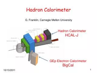
CMS HCALs Had Barrel: HB Had Endcaps:HE Had Forward: HF HO HB HE HF
HCAL : HE and HB HB HE
Optical Design for CMS HCALs Common Technology for HB, HE, HO
5mm HAD (143 cm) EM (165 cm) HF detector To cope with high radiation levels (>1 Grad accumulated in 10 years) the active part is Quartz fibers: the energy measured through the Cerenkov light generated by shower particles. • Iron calorimeter • Covers 5 > h > 3 • Total of 1728 towers, i.e. • 2 x 432 towers for EM and HAD • h x fsegmentation (0.175 x 0.175)
Issues for SLHC • Radiation Damage • Rate Effects • Bunch ID determination • Activation/access
Scintillator - Dose/Damage Current operational limit ~ 5 Mrad
Radiation damage to scintillators Dose per year at SLHV ECAL HCAL Barrel doses are not a problem. For the endcaps a technology change may be needed for 2 < |y| < 3 for the CMS HCAL.
Bunch ID: CMS HB Pulse Shape 100 GeV electrons. 25ns bins. Each histo is average pulse shape, phased +1ns to LHC clock 12 ns difference between circled histo’s no problem with bunch ID
Timing using calorimeter pulse shape 2003 Test Beam CMS HE Calculated event time (in clock cycles) Calculated event time (vertical scale) vs actual event time. CMS HE, 100GeV pions. Watch pile-up though. The faster the calorimeter, the less important pile-up will be.
HF Cerenkov Calorimeter Pulse Shape CMS HF Calorimeter 2003 Test Beam 25 ns Intrinsically very fast
Profitable R&D Directions? • Cerenkov calorimeters are rad-hard and fast good candidates for future colliders • Quartz fiber or plate • Gas cerenkov • New photon detectors low cost, small, rad-hard • Red-sensitive HPDs • Geiger-mode photodiodes • New scintillator materials rad-hard • New directions: • A number of new calorimeter concepts, some more realistic for a CMS calorimetry upgrade than others
A Blue Tiles Current materials Em 408-425nm Blue Green WLS WLS faster than Y11 EM 490-520nm Use in muon system and for triggering Areas of low/moderate radiation B/C Blue/Green – Green Tiles Em 490-510nm Green/Yellow WLS EM 550-560nm Benefits: Stays short of the “crevasse” in the transmission curve. In a region of “better” HPD QE. Potentially good system response. Scintillator R&D Approaches
Example of excitation and emission measurement: Standard vs New Materials
Averaged PMT pulses for a standard scintillation tile read out with multiclad WLS fibers
Readout for Red Scintillator Two Reasonable Choices DEP HPD with red photocathode ECAL Avalanche Photodiode Advantages Fits into existing RBX and Electronics Same power supply and control Small development costs optimize AR coating reduce dark count? DisadvantagesOnly 7% quantum efficiency in red Cost per tube is high ($150/ch) Advantages 85% quantum efficiency in the red Understood and in use in CMS Cost is only $30/ch No HV, bias is 200-500 V Disadvantages New fiber attachment system Modified RBX design Interface to QIE Need bias and temperature control
APD & Choice of electronics ECAL electronics? QIE with modifications? Off-Axis detector may use Pixelated APD (Ray Yarema) Comparison of HPD vs APD must be in the context of the preamplifier (noise and gain) as well as details of the APD operation: Gain, temperature, capacitance, etc… Prisca Cushman has made a number of numerical studies to compare APDs and HPDs
RadHard Scintillator Readout Upgrade A Number of investigations will be carried out in 2004 • Compare red sensitive HPD to APD • Design and build fiber interface to APD • Design and build interface of APD to QIE • Optimize APD operating conditions to HCAL
New Photodetector: SiPMs • The Silicon Photomultiplier is a Russian invention, reported by Boris Dolgoshein and colleagues at Moscow Engineering and Physics Institute, Lebedev Physical Institute, and Pulsar Enterprise (Moscow). • Ref: NIM A 504 (2003) 48 - 52; NIM A 442 (2000) 187-192 • SiPM consists of ~10**3 micropixels, size ~30microns, with very thin (0.75 micron) high field depletion layer. • Pixels are resistively isolated, each working in limited Geiger mode as “binary” devices. The pixels signals are ganged together by aluminum strips and the summed signal is effectively analog, with dynamic range limited by the number of pixels (<~ 60% occupancy for good linearity). • Gain ~10**6 Bias voltage ~25V Broad spectral sensitivity • Sees single pe, and resolves adjacent many-pe peaks with low noise • Works In high magnetic fields Time resolution ~30ps for 10 pe • Size ~few mm Cost $10 in large lots ($50 in small lots) • 5000 are at DESY for TESLA tile-fiber hadron calorimter
SiPMs • Where might we use (or have used) SiPMs? • CMS HCAL, except possibly for dynamic range. Present SiPM: ~100. If possible to increase pixel density to 2500 mm-2 and area to (1 cm)**2 ==> 6 x 10**4 dynamic range. Ease FE electronics (?). No HV cables or supply. Cheap phototransducer. • Use with RadHard Green/Red tile-fiber calorimeter for • High eta HE • S-CMS for SLHC • TOF for particle ID (a bit far-out) • I will try to use them (with small blocks of scintillator) for source-garaged verifiers for all the installed CMS drivers. A nice minor use of the high-gain, low-voltage and low cost. But hand-held survey meters can do this job adequately, as we do at CDF! • Use our imaginations…..
SiPMs • Issues: • How Rad tolerant? (and how much would that matter?) • Are pixel / device recovery times adequate for LHC (and SLHC) crossing rates? [higher pixel density ==> smaller C and Q per pixel, shorter RC. So probably worth pursuing.] • Availability, delivery times. I’m still waiting after nearly 2 months for a few samples @$50 per device from Elena Popova, to whom Dolgoshein referred me. Dolgoshein says PULSAR will do another large production run in April. I might be able to piggyback a certain number on that order. Boris did not say what micropixel count and density. • Will PULSAR develop larger area SiPM? higher micropixel density?
HE: Quartz plate and and Matching WLS Fiber • HE: Replace HE scintillaor in layers closest to IP with quartz plate for η > 1.5. We will also need to match the quartz light output to a WLS fiber. • Iowa, Fairfield and Mississippi will do a number of trials in 2004 to see if this proposal is viable.
HF Calorimetry • The HF detector at LHC has high-OH core, high NA, hard plastic cladding, QP fibers (quartz core plastic cladding) • Iowa group has tested fibers at LIL CERN 500 MeV electrons NIM A490 (2002) 444 • The HF detector will receive about 100 Mrad/year at eta=5 with accumulated dose 1-2 Grad/10 years
HF Calorimetry • The HF region will have much higher doses than LHC environment (1-2 Grad/year and about 20 Grad/10 years) • For high radiation doses must use no organic materials • We will test special quartz fibers with quartz cladding. These fibers are Silica/Silica, High-OH, UV enhanced, QQ (Quartz core/ Quartz cladding) with different type of buffer materials (Acrylic, Polymide, Aluminum) with different diameters (300, 600, and 800 micron) • Fibers will be given 5 x 10¹⁷ n/cm2, about 20 Grad(neutrons with energy > 0.1 MeV)in IPNS (Intense Pulsed Neutron Source)at Argonne National Laboratory • The range of 10-50 Grad will also be available at this facility. • We will test the induced attenuation vs wavelength, transmission of Xe light in the 350-800 nm range after irradiation. Also measure the tensile strength before and after the irradiation. • These measurements will be important for SLHC R&D for HCAL, HE, HF, ZDC, & CASTOR forward detectors.
Iowa Polymicro New Rad-hard Quartz fiber/plate project • Goals: • Determine if optical fibers are capable of functioning in a radiation environment 10 times the present CMS detector levels. • If yes, then explore what fiber designs would be best for the CMS detector upgrade. • Test candidate fiber materials –core, clad and buffer to determine suitable materials. • Fabricate/Purchase test fibers with materials from step 3. • Test candidate fibers for radiation hardness, mechanical and optical performance before and after irradiation. • Develop preliminary fiber specifications
Iowa Polymicro New Rad-hard Quartz fiber/plate project • Fiber Designs – conduct review of the fiber designs suitable for the CMS application. From this review, select the focus of the design and testing activities. Focus should be on the fiber design offering the most chances of success. There are way too many fiber designs to test all.
Gas Cerenkov S/V LHC Forward Calorimeter • Oleksiy Atramentov, John Hauptman, Nural Akchurin, Oesa Walker, Rohit Nabyar • CMS Note-00-007 “Velocity-of-light Gas …” • Jim Virdee suggested that we design a calorimeter for the SLHC • This work funded by LC R&D consortium (Luminosity monitor, 1.4 ns, 1MGy/y, large e/gamma backgrounds) • For SLHC, think of tungsten, hex rods, 1 meter depth, beta butylene, O. Atramentov, J.Hauptman, N. Akchurin CMS Note-00-007 “Velocity-of-light gas …” Jim Virdee suggested we design calorimeter for SLHC This work funded by LC R&D consortium
e- Calorimeter design • The Cerenkov light is generated by shower particles that cross gas gaps between absorber elements. • Shower particles co-move with the Cherenkov light as two overlapped pancakes. The width of these pancakes is about 12 ps. • Inside surfaces must be highly reflective at grazing incidence.
Gas Cherenkov Calorimeter: • Gas has index of refraction n = 1+, ( 10-3), therefore Cherenkov angle is small • and energy threshold for electrons is high • The Cherenkov photon signal exits the calorimeter volume at the velocity of light • Decay products from radioactivation of the calorimeter mass are below Ethand therefore invisible • A calorimeter made wholly of gas and metal cannot bedamaged by any dose of radiation.
Photon Production • Production of Cherenkov photons by 10 GeV electron transversing 2mm gas conduits in Pb (a simulation)
Geometries: now being simulated – G3 and G4 • Tubes – reflecting on inside • Hex rods – reflecting on outside • “Lasagna” separated functions of absorber material and reflecting surface • Other geometries …
DREAM Calorimetry:DREAM Prototype (Upstream) • The detector is made from 4 mm X 4mm copper tubes with a 2.5 mm dia hole in them. There are 19 hexagonal towers (38 Readout channels). There are 5580 copper tubes total. • The detector weighs 1030 kg. • 2 m deep copper is ~10 interaction lengths. • Effective rad.length is 20.10 mm and the Moliere rad is 20.35 mm 16.2 cm
DualReadout = Scintillator + Quartz • 69.3% Cu, scintillating fiber 9.4%, Cherenkov 12.6% and air is 8.7% • 3 scintillating and 4 clear fibers per hole. • Scintillator and the quartz fiber bundles are readout separately with R580 PMTs. • There are 270 tubes per tower. • Flat-to-flat measures 72 mm and contains >93% EM shower. • 38 PMTs are housed in a readout box behind the detector. Wratten 3 filter on scintillators. Quartz fiber Scintillating fiber SCSF-81J Kuraray, QP Polymicro, PJR-FB750 Toray.
Scintillator(rms/mean)=12.3% Quartz(rms/mean)=19.0% S(e/pi)=1.22 Q(e/pi)=1.56 Q(e/h) ~5 S(e/h) ~1.4 100 GeV Pions
Energy Resolution (100 GeV pions) Preliminary • The scintillating section of the detector measures 100 GeV pions with 12.3% resolution before correction. • Once the fluctuations in the EM energy deposition is removed using the information from the quartz section, the hadronic energy resolution improves. • After this correction, the energy resolution improves dramatically to 2.6%.
Remarks • The combination of scintillator and clear fibers gives a good handle to measure the electromagnetic fraction for each event which can be used to improve hadronic energy resolutions significantly. • If the beam energy is known, like test beams, the energy resolution can be improved by a factor of ~4-5. But this assumes the particle energy is already known. Beware. • If, on the other hand, Ebeam is treated as unknown, the improvement is ~2-3. Still a big factor. • At the limit, the energy resolution for electrons and the pions need to be the same once this source of fluctuation is removed. • Analysis continues. • Interesting but probably not applicable for a CMS upgrade
PPAC – a Rad Hard Detector Hadron The light color is solid metal. Detectors that sample the showerare shown in darker color.Detector near front end is for EM shower Some forward-angle calorimeters for the LHC will receive huge amounts of radiation, ~100 Grad. Need detector to be fast, simple, and radiation hard.
Iowa PPAC - a radiation hard detector • Three flat plates, separated by2 mm • Middle plate at high voltage • Outer plates hold atmospheric pressure • Filled with 10-40 torr of a suitable gas • Timing resolution better than 300 ps • Will test energy and time resolution at the Advanced Photon Source (APS) at Argonne • A simple and reliable device for samplingshowers from hadrons and photons. • For highest radiation levels must be made with no organic materials
Iowa PPAC - a radiation hard detector This PPAC detector concept can be developed as a candidate for luminosity monitor, HF and ZDC at SLHC.
Iowa PPAC - a radiation hard detector Planned tests with double PPAC • Test with EM showers using 80 ps bunches of 7 GeV electrons from the Advanced Photon Source, at Argonne National Laboratory • Test with low energy hadron showers using the 120 GeV proton test beam at Fermilab
PPAC vs. Scintillating tile • A radiation hard PPAC could be made as a drop in replacement for a scintillating tile in HE. • It would fit in the same space and produce a similar (but faster) signal • Front End electronics would have to be redesigned