Download
1 / 14
140 likes | 398 Views
Linac Coherent Light Source (LCLS) Low Level RF System New RF System Commissioning Experience April 16, 2007. Safety. Hazards in the LLRF system RF 1kW at 120Hz at 5uS = 0.6 Watts average, 2 Watt average amps at 2856MHz, 60W average amps at 476MHz Hazards – RF Burns

E N D
Linac Coherent Light Source (LCLS) Low Level RF SystemNew RF System Commissioning ExperienceApril 16, 2007
Safety • Hazards in the LLRF system • RF 1kW at 120Hz at 5uS = 0.6 Watts average, • 2 Watt average amps at 2856MHz, • 60W average amps at 476MHz • Hazards – RF Burns • Mitigation – Avoid contact with center conductor of energized connectors. All employees working with LLRF systems are required to have the proper training. • 110VAC Connector • Hazards - Shock • Mitigation - Don’t touch conductors when plugging into outlet. • All chassis are inspected by UL trained inspector (EEIP).
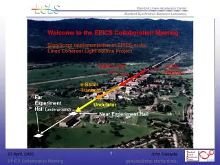
LCLS Layout P. Emma
Scope of Work for Injector Turn-on 1 • Linac Sector 0 RF Upgrade • All 3 RF Chassis completed and Installed • Control Module (IQPAU) needs modifications • Sector 20 RF distribution system - • Phase and Amplitude Controllers (PAC) - Operational • Phase and Amplitude Detectors (PAD) - Operational • Phased Locked Oscillator – Use SPPS unit for Turn On • LO Generator - Operational • Multiplier – 476MHz to 2856MHz - Operational • 4 distribution chassis - Operational • Laser Phase Measurement – Needs some signal processing • X-Band Reference – Chassis built, require testing and installation • LLRF Control and Monitor System • 1 kW Solid State S-Band Amplifiers – 5 units • PADs – 6 Klystron units in Fabrication • PADs – Gun, L0A, L0B, L1S – Operational : Tcav, L1X in test • PACs – Gun, L0A, L0B, L1S –Operational : TCav, L1X in test • Beam Phase Cavity • PAD in test • Pill box cavity with 2 probes and 4 tuners – Complete
Scope of Work for Injector Turn-on 2 • LLRF VME control system • Local feedback loops on RF phase and amplitude • RF Gun Cell loop tested in lab at 360 Hz and in operation at 10 Hz • L1-S loop tested in lab at 360 Hz and in operation at 30 Hz • L0-A and L0-B loops tested in lab at 100 Hz • Gun Tune temperature loop testing in progress • Event system and timing triggers configured for accelerate and standby • External interfaces • Beam-synchronous acquisition • LEM, SCP Correlation plots • Channel Archiver – active for all installed channels • Alarm Handler – initial layout done by J. Rock. Alarm limits TBD • Global beam-based longitudinal feedback on L0-B and L1-S - untested
SLAC Linac RF – New Control The new control system will tie in to the IPA Chassis with 1kW of drive power available. Reference will be from the existing phase reference line or the injector new RF reference I and Q will be controlled with a 16bit DAC running at 102MHz. Waveforms to the DAC will be set in an FPGA through a microcontroller running EPICS on RTEMS. Existing System
Processing RF Stations Gun – About 1 Week to Full Power L0A – About 2 Weeks to Full Power Most stations were and still are gassy by the klystron.
Processing RF Stations L0B – About 2 weeks to Full Power L1S – Easy 1 Week to Full Power
Gun High Power RF Pulse Shaped by PACL0A and L0B look similar Amplitude Waveform flat to +-2% Phase Waveform flat to +-2 Degrees Pulse width of 1.2uS and >600nS of waveguide eliminates klystron power change due to reflected power and need for circulator.
L1S High Power RF SLED Pulse Shaped by PAC SLED Amplitude Waveform Phase Waveform flat to +-2 Degrees Over fill time of structure
Operational Units • S-Band Reference System • Laser SPAC • Gun PAC • L0-A PAC • L0-B PAC • L1-S PAC
Injector/L1 Units Remaining to Commission • TCav PAC • Gun (done 4/12/07), L0-A, L0-B, L1-S, TCav PADs • Klystron PADs • Sector 0 IQPAU • X-Band System • VME based Feedbacks (Gun Cell Done) • Diagnostic data analysis
To Follow • PAC software – more analysis in FPGA • PAD software – evaluate speed • Second network – to send waveforms out while running • Switch to final network configuration putting embedded IOCs on private network • Switch access to waveforms to use CA gateway • VME – quantify CPU usage as each station is added