Download
1 / 50
510 likes | 622 Views
Introduction to Free Electron Laser and the Linac Coherent Light Source (LCLS). Science Undergraduate Laboratory Internships ( SULI 2010 ). Dao Xiang Beam Physics Department, SLAC June-22-2010. (Thank Y. Ding and P. Emma for providing many slides). Outline.

E N D
Introduction to Free Electron Laser and the Linac Coherent Light Source (LCLS) Science Undergraduate Laboratory Internships ( SULI 2010 ) Dao Xiang Beam Physics Department, SLAC June-22-2010 (Thank Y. Ding and P. Emma for providing many slides)
Outline • Discoveries in the field of x-rays • From x-ray tubes to free electron lasers • Incoherent and Coherent radiation • Physics of free electron laser • Linac Coherent Light Source (LCLS)
Discoveries in the field of x-rays • Discovery of x-rays The first Nobel prize was awarded to W.C. Röngtgen for discovery of x-rays X-rays wavelength: ~0.01 nm to 10 nm X-rays can penetrate through objects so they are widely used for imaging. • X-ray crystallography • Airport security The 1st “Medical” x-ray image • Medical physics 3
X-ray revolutionized the ultrafast and ultrasmall sciences • Discoverties in the field of x-rays • 19 Nobel prizes ? 4
Discoveries in the field of x-rays • DNA double helix Photo 51 DNA--Double helix • The secret to life (DNA) was discorvered with x-ray diffraction 5
Time scale Dt 1.3 sec 1 pico-second (ps) = 10-12 sec 0.3 mm 1 femto-second (fs) = 10-15 sec 0.3 m m 1 atto-second (as) = 10-18sec 0.3 nm In Hydrogen atom it takes about 150 as for an orbiting electron to circle the nucleus. 6
Understanding of a fast process can be greatly improved by freezing the action • All four of a horse’s feet leave the ground during a gallop? In 1878, E. Muybridge used a series of 12 stereoscopic cameras spaced at 21-inch intervals over 20 feet to capture a single horse stride, taking pictures at one thousandth of a second. 9
Capturing the ultrafast J. Hajdu, Uppsala U. t = 0 1-Å spatial resolution with hard x-rays t = 25 fs Atomic and molecular dynamics occur at the fsec-scale t = 50 fs Diffraction before Destruction for single molecule imaing
Probing the ultrasmall 1 mm 1 mm res 60 nm l = 32 nm Initial distribution Diffraction pattern Reconstructed distribution H. Chapman, et al, Nature Physics, 2, 839 (2006) Resolution is limited by radiation wavelength LCLS will push the resolution to Angstrom 11
History- From x-ray tubes to free electron lasers • 0th generation light source--- x-ray tubes Radiation from bremsstrahlung 13
History- From x-ray tubes to free electron lasers • 1st generation: synchrotron radiation in the parasitic mode e+ LCLS e- collider X-ray • 2nd generation: dedicated machines with x-ray generated in the bending magnet e- 14
History- From x-ray tubes to free electron lasers • 3rd generation: dedicated machines with x-ray generated in the undulators e- undulator Enhancement: 105 • 4th generation: free electron lasers High quality beam + ~100 m undulator Enhancement: 1010 15
Incoherent and coherent radiation • Radiation power is found by summing up the field for all the particles C A B • Incoherent radiation Random walk Phase is random in [0, 2π] 16
Incoherent and coherent radiation • Coherent radiation • Radiation wavelength longer than electron bunch length C A B Radiation is in phase • FEL: Microbunched beam gives coherent radiation 17
Basics of free electron lasers • Send a relativistic electron beam through a long undulator • Initial signal could be an input radiation such as a laser or it could be the spontaneous radiation generated in the undulator • Output radiation wavelength is determined by: • Wavelength can be changed by changing beam energy • High energy beam (~GeV) allows to generate x-ray radiation 18
Different kinds of free electron lasers Suited for optical X-ray possible Mirror & bunch train 1st FEL Suited for optical&UV Soft x-ray possible Input signal required Suited for ALL NO mirror&input signal High quality beam required LCLS 19
Brief history of free electron lasers • Proposed by John Madey in 1971 at Stanford University; J. Appl. Phys, 42, 1906 (1971) • First demonstration by Madey’s group in 1977 at Stanford University; Phys. Rev. Lett, 38, 892 (1977) “…possibility of partially coherent radiation sources in the … x-ray regions to beyond 10 keV.” 20
Brief history of free electron lasers • Stanford, Oscillator, 1977, 10.6 μm 24 MeV • UCLA&LANL, SASE, 1998, 12 μm 18 MeV • ANL, SASE, 2000, 530 nm 217 MeV • ANL, SASE, 2001, 355 nm 255 MeV • DESY, SASE, 2000, 109 nm 233 MeV • DESY, SASE, 2002, 95 nm 250 MeV • DESY, SASE, 2006, 13.7 nm 700 MeV • DESY, SASE, 2007, 6.7 nm 1 GeV • DESY, SASE, 2010, 5 nm 1.2 GeV • SLAC, SASE, 2009, 1.5 nm 4.3 GeV • SLAC, SASE, 2009, 0.15 nm 13.6 GeV “The success of LCLS has demonstrated that hard x-ray free electron laser works, and works well!” 21
Physics of free electron lasers • Resonant condition N S N S N S radiation l e- S N S N S N l Electron path length: Resonant wavelength: 22
Physics of free electron lasers • Bunching N S N S N S S N S N S N vx•Ex <0 vx.• Ex > 0 Due to sustained interaction, some electrons lose energy, while others gain energy modulation at e- losing energy slow down, and e- gaining energy catch up density modulation at (microbunching) Microbunched beam radiates coherently at , enhancing the process exponential growth of radiation power 23
electron beam photon beam undulator beam dump • Physics of free electron lasers • Bunching along the undulator SASE FEL starts up from noise log (radiation power) distance 24
Physics of free electron lasers • FEL slices Due to resonant condition, light overtakes e-beam by one radiation wavelength per undulator period Interaction length = undulator length optical pulse optical pulse z electron bunch electron bunch Slippage length = 1× undulator period (LCLS: slippage length = 1.5 fs, e-bunch length = 200 fs) • Each part of radiation pulse is amplified by those electrons within a slippage length (an FEL slice) 25
Physics of free electron lasers • Temporal coherence • SASE starts from noise • Many independent spikes • Final LCLS spike: • ~1000 1 = 0.5 fs! • No correlation between spikes Each slice lases independently! 26
Physics of free electron lasers • Transverse coherence Typical laser modes 27
Physics of free electron lasers • Transverse coherence--gain guiding More radiation is generated than is lost from diffraction Fundamental mode has the largest growth rate Z=25 m Z=38 m Z=50 m Z=88 m 28
Physics of free electron lasers • Transverse coherence--measurements LCLS measurements with a single wire Measurements at FLASH with double slits 29
Hard x-ray free electron lasers 2009 2011 2014 30
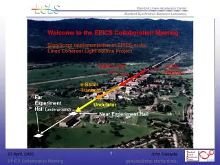
Injector (35º) at 2-km point Existing 1/3 Linac (1 km) (with modifications) New e- Transfer Line (340 m) X-ray Transport Line (200 m) Undulator (130 m) Near Experiment Hall (underground) Far Experiment Hall (underground) Linac Coherent Light Source at SLAC X-FEL based on last 1-km of existing linac 1.5-15 Å
Nov 2008… Commission Jan-Sep 2008 Commission Mar-Aug 2007 • LCLS • Accelerator layout (last 1 km of linac) 250 MeV z 0.19 mm 1.6 % 4.30 GeV z 0.022 mm 0.71 % 13.6 GeV z 0.022 mm 0.01 % 6 MeV z 0.83 mm 0.05 % 135 MeV z 0.83 mm 0.10 % Linac-X L =0.6 m rf= -160 Linac-0 L =6 m rf gun L0-a,b Linac-3 L 550 m rf 0° Linac-1 L 9 m rf -25° Linac-2 L 330 m rf -41° 25-1a 30-8c 21-3b 24-6d ...existing linac 21-1 b,c,d undulator L =130 m X BC1 L 6 m R56 -39 mm BC2 L 22 m R56 -25 mm undulator DL1 L 12 m R56 0 DL2 L =275 m R56 0 SLAC linac tunnel research yard
LCLS • Q 0.25 nC • f 30 Hz • Ecath 115 MV/m • gex,y 0.5 mm • Dt 6.5 ps e-(6 MeV) spectrometer dipole e- UV Drive Laser solenoid YAG screens RF gun Cathode (Cu) • Photocathode rf gun system
LCLS • Photocathode rf gun laser system Thales Drive Laser System (>98% uptime) 2009 Parameters: UV Wavelength 253 nm Energy on cathode 15 μJ Spatial profile ~uniform Time profile ~uniform Spot diameter 1.2 mm Pos. stability <3% radius Rep. rate 30 Hz Pulse length (fwhm) 6.5 ps Rise time (10-90%) ~2 ps Timing jitter <0.1 ps Up-time >98 % frequency tripled, chirped-pulse amplification system based on Ti:sapphire
LCLS • Photocathode rf gun
gex 0.43 mm 135 MeV 0.25 nC 35 A gey 0.46 mm • LCLS • Photocathode rf gun- Excellent performances
LCLS • Magnetic bunch compressor DE/E -z lower energy trajectory Tail (advance) center energy trajectory Head (delay) higher energy trajectory Introducing energy-position correlation into electron beam with off-crest acceleration Go through a system where the path length depends on beam energy
RF ‘streak’ V(t) sy S-band (2856 MHz) e- transverse RF deflector sz deflector OFF deflector ON • LCLS • Magnetic bunch compressor--beam diagnostics off-axis screen single-shot, absolute bunch length measurement • Deflector used to measure: • absolute bunch length, • time-sliced x-emittance, • time-sliced energy spread, • electron arrival time jitter
LCLS • Magnetic bunch compressor--Excellent performances nominal sz 2 mm
LCLS Beam Finder Wire (BFW) sand-filled, thermally isolated supports Cavity BPM (<0.5 m) 3.4-m undulator magnet Quadrupole magnet beam direction X-translation (in/out) Wire Position Monitor Hydraulic Level System • Undulator
LCLS • Undulator alignments-Excellent performances • Measure undulator trajectory at 4 energies (4.3, 7.0, 9.2, & 13.6 GeV) • Scale all linac & upstream transport line magnets each time • Calculate quadrupole and BPM alignment… (Matlab GUI) • Move quads and adjust BPM offsets for dispersion free trajectory RESULT: vary energy by factor of 3 trajectory changes by <10 mm
LCLS • Undulator--Prepared for the 1st lasing 112 meters of FEL Undulator Installed
LCLS • First Attempts at FEL Lasing – April 10, 2009 • 25 undulator magnets installed (slots 9-33) • Reduce peak current to 500 A (normally 3000 A) • Use beam screen installed 50 meters past undulator (FEE diagnostics not ready until late June) • Insert one undulator magnet at a time. Correct orbit, check field integrals, & spontaneous radiation pattern • After 10 undulators inserted, we begin to see a smaller spot at center of screen (still 500 A) FEL light! • So we insert 12 undulators and then slowly raise the peak current back to 3000 A…
LCLS • Saturation achieved – April 14, 2009 gex,y = 0.4 mm (slice) Ipk = 3.0 kA sE/E = 0.01% (slice) LG = 3.3 m Hard x-ray FEL works, and works well!
Final comments • X-ray was/is/will be an indispensible tool for biology, chemistry, physics, material sciences, etc. • The unique properties of X-ray free electron laser (high brightness + short pulse) will allow us to probe the ultrasmall and capture the ultrafast. • Free electron laser is not FREE; Hard x-ray FEL is not HARD. Thanks!