Digital Micromirror Devices (DMD)
510 likes | 836 Views
Digital Micromirror Devices (DMD). ECE 5320 – Mechatronics Utah State University Brett Rogers brett.rogers@aggiemail.usu.edu. Outline. Major applications Basic Working Principle Illustrated A Typical Sample Configuration in Application Specifications Limitations History

Digital Micromirror Devices (DMD)
E N D
Presentation Transcript
Digital Micromirror Devices (DMD) ECE 5320 – Mechatronics Utah State University Brett Rogers brett.rogers@aggiemail.usu.edu
Outline • Major applications • Basic Working Principle Illustrated • A Typical Sample Configuration in Application • Specifications • Limitations • History • Links and Other Resources • Reference list
Major Applications • Digital Light Processing (DLP) projectors[5] • Volumetric Displays[7] • Print Setting[7] • Printed Circuit Board (PCB) Manufacturing[7] • Semiconductor Patterning[7] • Holographic Data Storage[7]
Functional Overview • Array of tiny mirrors (up to 2 million) • Each mirror is 16µm x 16µm • Each mirror pivots about a fixed axis1 • Each mirror acts as a digital light switch • ON: Light is reflected to desired target • OFF: Light is deflected away from target • Pulse Width Modulation (PWM) techniques are used to perform digital light modulation • MEMS: fabrication process similar to CMOS
Conventional DMD Construction Source: Jeffery B. Sampsell; “An Overview of the Performance Envelope of Digital Micromirror Device (DMD) Based Project Display Systems”; Texas Instruments Source: Larry J. Hornbeck; “Current Status of the Digital Micromirror Device (DMD) for Project Television Systems;” Texas Instruments
Mirror Mounting Mechanism • Each mirror is mounted on Hinge Support Posts • Each mirror rotates about the posts • Torsion hinge restores the mirror to its default horizontal state when no power is applied to the circuit Source: Larry J. Hornbeck; “Current Status of the Digital Micromirror Device (DMD) for Project Television Systems”; Texas Instruments
Mirror Rotation • Each mirror rotates +/- 10° for total rotational angle of 20° • Landing Electrode provides stop pad for the mirror and allows precise rotational angles Source: Larry J. Hornbeck; “Current Status of the Digital Micromirror Device (DMD) for Project Television Systems”; Texas Instruments
Bias Bus & Address Electrodes • Bias/Reset Bus provides stop pad and connects all mirrors to allow for a bias/reset voltage waveform to be applied to the mirrors • Address electrodes are connected to an underlying SRAM cell’s complimentary outputs Source: Larry J. Hornbeck; “Current Status of the Digital Micromirror Device (DMD) for Project Television Systems”; Texas Instruments
SRAM Cell • Complimentary SRAM cell outputs connected to the address electrodes actuate the mirrors by electrostatically attracting/repelling the free corners of the voltage-biased mirrors Source: Larry J. Hornbeck; “Current Status of the Digital Micromirror Device (DMD) for Project Television Systems”; Texas Instruments
Modern DMD Construction Source: Larry J. Hornbeck; “Current Status of the Digital Micromirror Device (DMD) for Project Television Systems”; Texas Instruments Source: Gary A. Feather; “The Digital Micromirror Device for Project Display”; Texas Instruments
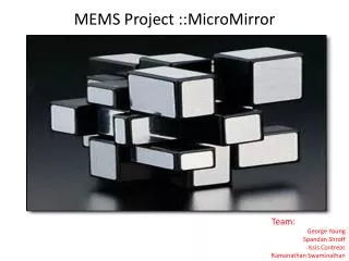
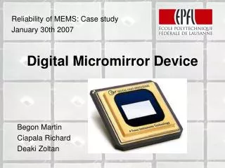
3-D Model Source: Begon Martin, Ciapala Richard, Deaki Zoltan; “Reliability of MEMS: Case Study”; Ecole Polytechnique Federale De Lausanne
DMD As An Actuator/Sensor • DMDs have these actuating components • Rotation caused by torsion spring • Rotation caused by electromagnetic forces • DMDs have these sensing components: • Bias/Reset bus electrode • Address bus electrode • Electromagnetic properties of the mirror • SRAM cell
Application of DMD in DLP • DMD is the technology of Digital Light Processing (DLP) projectors • DMD reflects incident light toward or away from optical lens • Optical lens projects image on screen • Each mirror of DMD corresponds to one pixel of projected image
Three-Pixel DLP Projector Example Source: Lars A. Yoder; “An Introduction to the Digital Light Processing (DLP) Technology”; Texas Instruments
Full DLP System Pictorial Overview Source: Larry J. Hornbeck; Digital Light Processing: A New MEMS-Based Display Technology; Texas Instruments
DLP Integrated Circuit Source: http://www.asme.org/Communities/History/Landmarks/53_Digital_Micromirror_Device.cfm
DMD Specifications • Mirror Size = 16µm x 16µm (17µm centers) [3] • Resonant Frequency = 50kHz [3] • Switching Time < 10µSec [4] • Total Rotational Angle = 20°[3] • Total Efficiency of Light Use > 60%[6] • Fill Factor per Mirror = 90%[6]
Potential Energy of Mirror Potential Energy of Mirror as a Function of Angle and Voltage Bias (address voltage = 0) Source: Larry J. Hornbeck; “Digital Light Processing: A New MEMS-Based Display Technology”; Texas Instruments
Switching Response Three variables are plotted as a function of time: the bias/reset voltage, the cross-over transition from +10 degrees to -10 degrees, and the same-side transition for a mirror that is to remain at +10 degrees. Shortly before the reset pulse is applied, all the SRAM memory cells in the DMD array are updated. The mirrors have not responded to the new memory states because the bias voltage keeps them electromechanically attached.[5] Source: Larry J. Hornbeck; “Digital Light Processing: A New MEMS-Based Display Technology”; Texas Instruments
DMD Limitations: Hinge Memory[8] • Hinge memory is largest failure of DMD • Occurs when mirror remain in one position for extended period of time • Torsion hinge no longer restores mirror to perfectly horizontal position • Bias voltage must increase to compensate
Bias Voltage Compensation Source: Begon Martin, Ciapala Richard, Deaki Zoltan; “Reliability of MEMS: Case Study”; Ecole Polytechnique Federale De Lausanne
Mirror Affected by Hinge Memory Front mirrors are perfectly horizontal, while rear mirrors maintain a residual tile due to hinge memory. Source: Begon Martin, Ciapala Richard, Deaki Zoltan; “Reliability of MEMS: Case Study”; Ecole Polytechnique Federale De Lausanne
Hinge Memory Lifetime Source: Michael R. Douglas; “DMD reliability: a MEMS success story”; Texas Instruments
History • Developed by Texas Instruments (TI) [2] • DOD initially funded TI to develop a light modulator [2] • Project Team Leader: Dr. Larry Hornbeck [2]
History: From Analog to Digital I[2] • Deformable Mirror Device [2] • Analog Version of Digital Micromirror Device • Work began in 1977 • Analog voltage across air gap deformed mirror to produce different light intensities • Idea was scrapped in 1986
History: From Analog to Digital II[2] • Digital Micromirror Device [2] • Digital approach to light modulation • Use pulse width modulation (PWM) principles to turn the mirror “on” and “off” • First DMD was built and tested in 1987 • Unlike the Deformable Mirror Device, DMD does not change light intensity. But human eye integrates the Pulse Width Modulated signal to form different shades of color
Web Links and Other Information • Texas Instrument’s Official DLP Site: http://www.dlp.com/ • Flash Demo of DLP: http://www.dlp.com/includes/demo_flash.aspx • http://en.wikipedia.org/wiki/Digital_micromirror_device • http://www.audioholics.com/education/display-formats-technology/display-technologies-guide-lcd-plasma-dlp-lcos-d-ila-crt/display-technologies-guide-lcd-plasma-dlp-lcos-d-ila-crt-page-2
Quote “If you’re afraid to fail, then your actions may not be as bold, aggressive or creative as you need them to be in order to accomplish your goal. You may play it so conservative you never get there.”2 - Dr. Larry Hornbeck
References • What is DLP?,; http://focus.ti.com/dlpdmd/docs/dlplearningdetail.tsp?sectionId=62&tabId=2249 • “The Digital Micromirror Device, A Historical Landmark”; Texas Instruments and The American Society of Mechanical Engineers (ASME); 1996; http://www.asme.org/Communities/History/Landmarks/53_Digital_Micromirror_Device.cfm • Gary A. Feather, David W. Monk; “The Digital Micromirror Device for Project Display”; 1995 International Conference on Wafer Scale Integration • Larry J. Hornbeck; “Current Status of Digital Micromirror Device (DMD) for Projection Television Applications”, 1993 • Larry J. Hornbeck; “Digital Light Processing: A New MEMS-Based Display Technology”; Texas Instruments • Lars A. Yoder; “An Introduction to the Digital Light Processing (DLP) Technology”; Texas Instruments • Dana Dudley, Walter Duncan, John Slaughter; “Emerging Digital Micromirror Device (DMD) Applications”; Texas Instruments • Begon Martin, Ciapala Richard, Deaki Zoltan; “Reliability of MEMS: Case Study”; Ecole Polytechnique Federale De Lausanne • Michael R. Douglas; “DMD reliability: a MEMS success story”; Texas Instruments