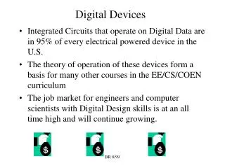
Digital Devices
Digital Devices. Digital Devices. Implementing logic circuits Shorthand notation Electrical characteristics. Implementing Logic Circuits. There are several varieties of transistors – the building blocks of logic gates – the most important are:

Digital Devices
E N D
Presentation Transcript
Digital Devices • Implementing logic circuits • Shorthand notation • Electrical characteristics
Implementing Logic Circuits • There are several varieties of transistors – the building blocks of logic gates – the most important are: • BJT (bipolar junction transistors) – one of the first to be invented. • Now largely supplanted by FET (field effect transistors), in particular Metal-oxide semiconductor types (MOSFET’s). • MOSFET’s are of two types: NMOS and PMOS
TTL and CMOS • Connecting BJT’s together gives rise to a family of logic gates known as TTL • Connecting NMOS and PMOS transistors together gives rise to the CMOS family of logic gates. BJT MOSFET (NMOS, PMOS) transistor types TTL CMOS logic gate families
TTL faster strong drive capability CMOS lower power consumption simpler to make greater packing density better noise immunity Electrical characteristics • Complex ic’s contain many millions of transistors. • If constructed entirely from TTL type gates would melt • A combination of technologies may be used. • CMOS has become most popular and has had greatest development
Electrical characteristics of logic families • Important characteristics are: • VOHmin min value of output recognised as a ‘1’ • VIHmin min value input recognised as a ‘1’ • VILmax max value of input recognised as a ‘0’ • VOLmax max value of output recognised as a ‘0’ • Values outside the given range are not allowed.
Noise Margin • If noise in the circuit is high enough it can push a logic 0 up or drop a logic 1 down into the “illegal” region • This is the magnitude of the voltage required to reach this level is the noise margin • Noise margin for logic high is: NMH = VOHmin – VIHmin Vohmin Vihmin Vilmax Volmax
Further Important Characteristics • The propagation delay (tpd) which is the time taken for a change at the input to appear at the output • The fanout, which is the maximum number of inputs that can be driven successfully to either logic level before the output becomes invalid
TTL - Example SN74LS00 • Recommended operating conditions • Vcc supply voltage 5V ± 0.5 V • input voltages VIH = 2V VIL = 0.8V • Electrical Characteristics • output voltage (worst) VOH = 2.7VVOL = 0.5V • Maximum input currents IIH = 20µA IIL = -0.4mA • propagation delay tpd = 15 nS • noise margins for a logic 0 = 0.3V for a logic 1 = 0.7V • Fan-out 20 TTL loads 5 Volt Input Range for 1 Output Range for 1 2.7 2.0 0.8 Input Range for 0 Output Range for 0 0.5 0 Volt
Electronic Combinational Logic Within each of these families there is a large variety of different devices • We can break these into groups based on the number gates per device • For this course we will just look at the first 2: SSI and MSI
SSI Devices • Each package contains a code identifying the package N74LS00 Manufacturers Code N = National Semiconductors SN = Signetics Family L LS H Member 00 = Quad 2 input NAND 02 = Quad 2 input Nor 04 = Hex Invertors 20 = Dual 4 Input NAND Specification
P = A.B+A.C Connections on 74LS00 • Show how a single 74LS00 could be used to implement the function 14 13 12 11 10 9 8 1 2 3 4 5 6 7
Connections on 74LS00 • Can be done in three steps: • Draw the equivalent circuit • Convert to NAND gates only • Work out the pin connections
Pin Connections 14 13 12 11 10 9 8 • One solution, check it! • Inputs • A connects to 1,2 and 13 • B connects to 12 • C connects to 5 • Outputs • P connects to 8. • Pins • 11 to 10 • 3 to 4 • 6 to 9 1 2 3 4 5 6 7
MSI Devices • Commonly used functions such as the adder and the BCD-to-seven-segment display are implemented as MSI devices
BCD to SSD outputs to segments BCD inputs
Programmable Logic Devices • Programmable devices have their functionality programmed before they are first used. • Range in complexity from 100’s to 10,000’s of logic gates.
PLD’s • Commonly use logic gates based on diodes: Vdd – logic 1 eg AND gate Ry a both at logic 1 y = a.b b if either a or b is pulled down to Vss, logic 0, then y is pulled to zero also More inputs can be made by adding more diodes. Source: Bebop to the Boolean Boogie, Clive Maxfield, Technology Publishing, ISBN 1-878707-22-1
Exercise • Consider how an OR gate might be implemented: a b Ry a and b are at logic ? output y is on upper or lower line Vdd – logic 0
Fusible link PLD’s • Each diode has an associated link (fuse) • The can be “blown” with a high voltage pulse • Thus the arrays of diodes can be programmed (one-time).
Inputs OR AND products plane plane outputs PLD’s Most of these devices are based on a two level structure (sum of products form).
In practice this might be represented as: inputs PLD notation • The fusible links are made at the x’s, otherwise blown. A B C D D + A A.C + B.C outputs
Inverted inputs A B inputs A.B + A.B = B A + B outputs
PLD’s • The main types of PLD include: • PLA’s (programmable logic arrays) • PAL’s (programmable array logic) • PROM’s (programmable read only memory)
PLA’s A B A programmable logic array (PLA) has all links programmable in both AND and OR arrays. Very flexible. Many applications don’t require such flexibility
A A B B A F4 F1 1 P 3 B 2 F5 F8 PALs • AND plane programmable • OR plane fixed • Not so flexible • Operate faster because hard-wired OR’s switch quicker than programmed links. programmable links
A A B B A F4 F1 1 P 3 B 2 F5 F8 PAL’s • P = A.notB + notA.B • Use gate 1 to implement the 1st product term and gate 2 to implement the second • First term blow F2 and F3 • Second term blow F5 and F8
PALs Shorthand Notation A B C D E P P = A.C.D
data address ROM PROMs • AND array is pre-defined • OR array is programmable • Output of AND plane contains a signal for each of the possible input combinations • Memory device where each address applied to inputs returns a programmed value
PROM A B address 0 address 1 address 2 address3 programmable OR array
C A B S C in out 0 0 0 0 0 0 0 1 1 0 0 1 0 1 0 0 1 1 0 1 1 0 0 1 0 1 0 1 0 1 1 1 0 0 1 1 1 1 1 1 PROMs Example: The full adder
Reprogrammable PLD’s • EPROMS are like PROM’s except that they can be re-used. • Ultra-violet light is used to restore the fusible links • This is shone through a quartz window on top of the chip • Useful for testing and debugging before PROM’s are manufactured.
Custom and Semi-custom Integrated Circuits • Custom Chips: where the chips are designed from scratch • Very time consuming and expensive (Need to manufacture >105 to be economic) • Semi-custom Chips: where most of the design is already done and designer only has to make the final connections
What you should be able to do: • State the principal characteristics of TTL and CMOS logic gate families. • Define key terms such as: • fan-out • propagation delay • noise margin • Describe the key features of the range of PLD’s: PLA, PAL, PROM. • Convert a (simple) shorthand PAL diagram to a logic expression.