Testing Workshop: Reactive Capability Testing
Testing Workshop: Reactive Capability Testing. Bill Blevins Carmen Tillman Sandip Sharma. Outline. Clarify how Nodal Protocols for Voltage Support and Unit Reactive Test are related and dependent Define CURL and URL

Testing Workshop: Reactive Capability Testing
E N D
Presentation Transcript
Testing Workshop:Reactive Capability Testing Bill Blevins Carmen Tillman Sandip Sharma
Outline • Clarify how Nodal Protocols for Voltage Support and Unit Reactive Test are related and dependent • Define CURL and URL • Review telemetry requirements for Unit Reactive Testing for Conventional and IRR units • Discuss Coordinated Vs. Non-Coordinated Testing • Review NDCRC Form • Demonstrate CURL data use in ERCOT ISO Grid Operations • Feedback from Market Participants • Identify topics which still require additional clarification • Suggested changes to NDCRC tool
Nodal Protocols – Reactive Capability • NP 3.15 (2): Units Required to Provide VSS • All Generation Resources (including self-serve generating units) that have a gross generating unit rating greater than 20 MVA or those units connected at the same Point of Interconnection (POI) that have gross generating unit ratings aggregating to greater than 20 MVA, that supply power to the ERCOT Transmission Grid, shall provide Voltage Support Service (VSS). • Nodal Protocol 3.15 • Voltage Support Service Requirements {POI} • +/- 0.95 power factor (lead/lag) at Maximum Net MW Output • URL • Nodal Protocol 8.1.1.2.1.4 • Maximum Reactive Capability of the Unit • CURL Validation {Generator Terminals/Gross} • “How to Guide”: Nodal Operating Guide 3.3.2 • NP 3.15 (3): Reactive Requirement (POI) • An over-excited (lagging or producing) power factor capability of 0.95 or less determined at the generating unit's maximum net power to be supplied to the ERCOT Transmission Grid and at the transmission system Voltage Profile established by ERCOT, both measured at the POI; • (b) An under-excited (leading or absorbing) power factor capability of 0.95 or less, determined at the generating unit's maximum net power to be supplied to the ERCOT Transmission Grid and at the transmission system Voltage Profile established by ERCOT, both measured at the POI; • NP 8.1.1.2.1.4 (2): Reactive Testing Requirement • The Resource Entity shall conduct reactive capacity qualification tests to verify the maximum leading and lagging reactive capability of all Generation Resources required to provide VSS. Reactive capability tests are performed on initial qualification and at a minimum of once every two years. ERCOT may require additional testing if it has information indicating that current data is inaccurate. The Resource Entity is not obligated to place Generation Resources On-Line solely for the purposes of testing. The reactive capability tests must be conducted at a time agreed to in advance by the Resource Entity, its QSE, the applicable TSP, and ERCOT.
URL and CURL Defined Unit Reactive Limit - URL Corrected Unit Reactive Limits - CURL Defined in Nodal Operating Guides 3.3.2 The corrected reactive capability curve establishes the Corrected Unit Reactive Limits (CURL) at the unit terminals that ERCOT Planning and ERCOT Operations will use for their studies. Leading and lagging reactive gross output • Nodal Protocol Definitions and Acronyms • The maximum quantity of Reactive Power that a Generation Resource is capable of providing at a 0.95 power factor at its maximum real power capability. • Leading and lagging Net MVAR
CURL and URL Typically limited by prime mover. Generator is sized greater than turbine.
CURL Components “Typical Generator Capability Curve and Operating Limits for a cylindrical rotor generator” from IEEE PES-PSRC Paper “COORDINATION OF GENERATOR PROTECTION WITH GENERATOR EXCITATION CONTROL AND GENERATOR CAPABILITY”
Static and Dynamic Reactive Devices (Power World Example) Each component is capable of providing reactive but is modeled separately.
Tested Reactive Capability Measured and Telemetered Gross Real and Reactive Power should be Telemetered during the Reactive Capability Test.
Gross MW and MVAR Telemetered for IRR Testing POI • IRR units are modeled at the collector bus on the low side of the GSU • The gross reactive output is the measured value at the collector bus with no static reactive devices included GROSS MW & MVAR (CT and PTs) GSU 138 kV/ 34.5 kV 34.5 kV Collector Bus CB CB Static or Dynamic Reactive Devices Feeders
Coordinated Vs. Non-Coordinated Reactive Capability Tests Coordinated Test Non-Coordinated Test 2 Hours Notice Required for all parties No assistance from TSP or ERCOT needed to adjust voltage at the POI No Adjusting Transformer Taps No Switching nearby Transmission Static Reactive Devices Not Recommended for Units testing as a requirement of Part 3 of the COD Checklist • ERCOT and TSP given a minimum of 48 hour notice of testing. ( An “ERCOT Operating Procedure Document Request for Unit Testing” should be submitted) • Included in the notice: • Date of Testing • Net MVAR Leading and/or Lagging that will be experienced on the TSPs transmission system during the test • CURL • Estimated MW output • TSP given confirmation prior to test date that system conditions can be made favorable for a specified leading or lagging reactive test on the requested test date • TSP approves reactive testing • ERCOT approves reactive testing
When should a Resource Entity conduct a Coordinated Reactive Test? • If a RE is unable to test within 90% of the URL/CURL with a “non-coordinated” test then a “coordinated” test should be performed. • For initial testing the RE determines whether “coordinated” or “non-coordinated” reactive capability testing is appropriate. For additional information for “coordinated” and “non-coordinated” refer to Nodal Operating Guides section 3.3.2.3 and 3.3.2.2.
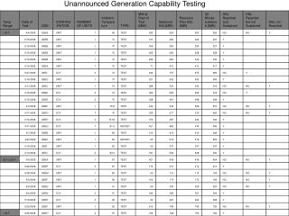
NDCRC Unit Reactive Test Form Process & timeframe for ERCOT to review & respond is between 2 weeks to a month
NDCRC Unit Reactive Test Form • Tested Reactive Capability Section is were Gross and Net MW and MVAR values are entered • These values must align with historical telemetered data to be considered valid
NDCRC Typical Unit Reactive Test – Data Points 6 Points which could be used to recreate the attached CURL These values should be the remain constant for a given unit Those entering the Test Form Should now receive automatic notifications that a review is complete whether the test is approved or rejected
NDCRC IRR Unit Reactive Test The Max Capability is the capacity of commissioned reactive devices at the site. The Tested Capability is the magnitude of MVAR contributed from the commissioned reactive devices during the test.
CURL DATA USE • Process for CURL Data Retrieval: • Perform Reactive Capability Test • Submit Test Results and CURL in NDCRC • Test Results are Reviewed • When Approved, the RARF should be updated (as needed) to reflect the CURL which was submitted in NDCRC within 10 business days • Nodal Protocol 3.7 (b): “ • The QSE or Resource Entity must update any Resource Parameter for a specific Resource…(b) Within ten Business Days of completion of a reactive capability test to reflect the results of the test” • Four Data Points submitted in the RARF are: • Incorporated in EMS model • Real Time • VSAT • Incorporated in Seasonal Studies • Planning Models
FEEDBACK • Identify topics which still require additional clarification • Additional Detail? • Examples? • Suggested changes to NDCRC tool • Changes to HELP documentation? • Add/Remove Fields? • More User-Friendly format? • Point of contact. Bill Blevins bblevins@ercot.com
Four basic WTG types • Type 1: Wound rotor induction generator • Type 2: Wound rotor induction generator with variable rotor resistance • Type 4: Full back-to-back converter interface between grid and turbine • Type 3: Doubly-fed induction generator (DFIG)
Protocol Language • 3.15 (4) Generation Resources required to provide VSS whose installations initially began operations on or after September 1, 1999, except as noted below, must have and maintain a URL which has an over-excited (lagging) power factor capability of 0.95 or less and an under-excited (leading) power factor capability of 0.95 or less, both determined at the generating unit's maximum net power to be supplied to the transmission grid and at the transmission system Voltage Profile established by ERCOT, and both measured at the point of interconnection to the TSP.
Other Protocol defined terms • High Emergency Limit (HEL) - Limit established by the QSE describing the maximum temporary unsustainable energy production capability of the Resource. This limit must be achievable for a time stated by the QSE, but not less than 30 minutes. • High Sustained Limit-(HSL for a Generation Resource)- Limit established by the QSE, continuously updated in Real Time, that describes the maximum sustained energy production capability of the Resource. • Net Dependable Capability - The maximum sustained capability of a Resource as demonstrated by performance testing. • Unit Reactive Limit - The maximum quantity of Reactive Power that a Generation Resource is capable of providing at a 0.95 power factor at its maximum real power capability.
URL and HSL Field Current Constraint (Typical limit) Unit Reactive Limit (URL) Lag Armature Current Constraint (Typical limit) Maximum Gross power output typically limited by the Turbine(Generators are typically sized greater than the Turbine) Under Excitation Constraint(Typical limit) Curve defined by Manufacturer (D-Curve) or CURL as updated by testing after commercial operations begins Test must fall within 90% of the Curve provided by the Resource Lag +MVAR .95 pf Lagging Maximum Net power output HSL typically Real Power Test loading for Lagging Test done at >60% HSL for IRR or above 95% HSL for Thermal Unit Real Power Test loading for Leading Test done at <60% HSL for IRR or at typical loading for low load conditions for Thermal Unit Net or Gross MW Lead -MVAR .95 pf Leading Unit Reactive Limit (URL) Lead Test must fall within 90% of the Curve provided by the Resource
The Question • Is the “maximum net power to be supplied to the transmission grid” the HSL?