OpenGL Modeling Basics and View Space Transformation Guide
Learn about OpenGL modeling basics, the graphics pipeline, and transforming objects in the view space for optimal rendering. Discover how to define view space, perform projection, and work with cameras in computer graphics.

OpenGL Modeling Basics and View Space Transformation Guide
E N D
Presentation Transcript
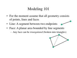
Modeling 101 • For the moment assume that all geometry consists of points, lines and faces • Line: A segment between two endpoints • Face: A planar area bounded by line segments • Any face can be triangulated (broken into triangles)
Modeling and OpenGL • In OpenGL, all geometry is specified by stating which type of object and then giving the vertices that define it • glBegin(…) …glEnd() • glVertex[34][fdv] • Three or four components (regular or homogeneous) • Float, double or vector (eg float[3]) • Chapter 2 of the red book
Rendering • Determine where each object should go in the image • Determine which object is in front at each pixel • Determine what color it is
Graphics Pipeline Watt Ch 5 and 6 • Graphics hardware employs a sequence of coordinate systems • The movement of geometry through these spaces is considered a pipeline Local Coordinate Space World Coordinate Space View Space 3D Screen Space Display Space
Local Coordinate Space • It is easiest to define individual objects in a local coordinate system • For instance, a cube is easiest to define with faces parallel to the coordinate axis • Key idea: Object instantiation • Define an object in a local coordinate system • Use it multiple times by copying it and transforming it into the global system
Global Coordinate System • All the objects in the world are transformed into one coordinate system - the global coordinate system • Lighting is defined in this space • The camera is defined with respect to this space • Some higher level operations, such as advanced visibility computations, can be done here
View Space • Associate a set of axes with the image plane • One normal to the image plane • One up in the image plane • One right in the image plane • Some camera parameters are easiest to define in this space • Focal length, image size
3D Screen Space • Transform view space into a cube • Parallel sides make things easier • Task to do: • Rasterization - decide which pixels are covered • Hidden surface removal - decide what is in front • Shading - decide what color things are
Display Space • Convert the virtual screen into real screen coordinates • Drop the depth coordinates and translate • The windowing system takes care of this
OpenGL and Transformations • OpenGL combines all the transformations up to view space into the MODELVIEW matrix • View space to Screen Space is done with the PROJECTION matrix • Matrix calls multiple some matrix M onto the current matrix C: CM • Set view transformation first, then set transformations from local to world space
Defining View Space • View space is defined by location of three mutually perpendicular axes in world space • Translation, rotation and scaling can take points in world space to points in view space • Typically defined by: • Center of the image plane in world space: View Reference Point (VRP) • The normal to the image plane: View Plane Normal (VPN) • A vector in world space that should be “up” in view space (VUP)
z View reference point and view plane normal specify film plane. Up vector gives an “up” direction in the film plane. vector v is projection of up vector into film plane = (n x vup) x n u is chosen so that (u, v, n) is a right handed coordinate system; i.e. it is possible to rotate (x->u, y->v, z->n) (and we’ll do this shortly). VRP, VPN, VUP must be in world coords W o r l d c o o r d i n a t e s x y U p v e c t o r V i e w r e f e r e n c e u p o i n t v n V i e w p l a n e n o r m a l
World to View Space • Translate by subtracting VRP • Rotate by amount that aligns camera axes with world axes: • All done for you in OpenGL: • gluLookAt takes the VRP, a point along the VPN, and VUP • Multiplies the required transformation onto the current transformation (normally the identity)
Default OpenGL Camera • The default OpenGL image plane has u aligned with the x axis, v aligned with y, and n aligned with z • Means the default camera looks along the negative z axis • Makes it easy to do 2D drawing (no need for any view transformation)
Left vs Right Handed View Space • You can define u as right, v as up, and n as toward the viewer: a right handed system uv=n • Advantage: Standard mathematical way of doing things • You can also define u as right, v as up and n as into the scene: a left handed system vu=n • Advantage: Bigger n values mean points are further away • OpenGL is right handed
Projection • The conversion from view space to screen space is called projection • Two general classes: • Orthographic, or parallel, projection • Perspective projection
Orthographic Projection • Points project along rays perpendicular to the image plane • Just drop the n coordinate, and maybe scale and translate • OpenGL: glOrtho(…) • Sets the appropriate projection matrix
Abstract camera model - box with a small hole in it Pinhole cameras work in practice - camera obscura, etc Perspective Projection
Parallel lines meet common to draw film plane in front of the focal point
Vanishing points • Each set of parallel lines (=direction) meets at a different point: The vanishing point for this direction • Sets of parallel lines on the same plane lead to collinear vanishing points: the horizon for that plane • Easy examples • corridor • higher = further away • Good way to spot faked images