Download
1 / 29
330 likes | 999 Views
Optical Wireless Communications. Prof. Brandt-Pearce Lecture 4 Visible Light Communications. Visible Light Communications (VLC). Introduction Applications White LED Illuminance Distribution Channel Model Challenges and Solutions. Visible Light Communications (VLC).

E N D
Optical Wireless Communications Prof. Brandt-Pearce Lecture 4 Visible Light Communications
Visible Light Communications (VLC) • Introduction • Applications • White LED • Illuminance Distribution • Channel Model • Challenges and Solutions
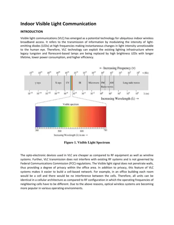
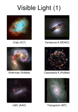
Visible Light Communications (VLC) • Visible light is only a small portion of the electromagnetic spectrum. • (Ref: Wikipedia) • Dates back to 1880, when Alexander Graham Bell invented the photophone • VLC is used for • Vehicle to vehicle communication • Networking in indoor environments
Indoor VLC • Can provide network access at • Home • Office • Shopping Center • Plane • Hospital • Convention Centers
Indoor VLC • Advantages • Safe for health • Secure • No interference on RF signals • High speed • Confined to small geographical area • Challenging Problems • Connectivity while moving • Multiuser support • Dimming • Shadowing • Confined to small geographical area
Indoor VLC Light-emitting-diodes (LED) are preferred sources for dual purpose of lighting and data communications • Eye-safety regulations (compared to Laser) • Longevity • Lower cost • Are mercury free • Less consumption • High speed • Have smaller and compact size • Minimum heat generation • higher tolerance to humidity • A much higher energy conversion efficiency (white LEDs with luminous efficacy greater that 200 lm/W are now available)
Rival Technologies • WiFi • Has limited capacity, and cannot increase it easily, because it covers a wide area, services potentially many users, and limited bandwidth. Higher order modulation of limited use since SNR limited. • E.g., office buildings, conference centers, stadiums • Bluetooth • Single user system for personal area communications. Very small range and low data rate. Less shadowing so good around moving people. • E.g., wireless microphones • Millimeter Wave? UWB? 7
White LEDs Two technologies in white LEDs • Phosphor-based LEDs • This technique involves the use of blue LED coated with a phosphor layer that emits yellow light • The phosphor layer absorbs a portion of a short wavelength light emitted by the blue LED and then the emitted light from the absorber experiences wavelength shift to a longer wavelength of yellow light • Are cheap and are less complex
White LEDs • Trichromatic • Generates white light by combining red (~625 nm), green (525 nm), and blue (470 nm) (RGB) in a correct proportion • Are high-speed • Enables color control • Typically, these triplet devices consist of a single package with three emitters and combining optics • Are attractive for VLC as they offer the possibility of wavelength division multiplexing (WDM)
White LEDs • The most important factor in VLC is the switching properties of the visible LEDs • They have the ability to be switched on and off very rapidly thereby making it possible to impress data on their radiated optical power/intensity • Modulation speed of white LEDs • is limited due to the relaxation time of the LEDs • BW of trichromatic LEDs < 20 MHz • BW of phosphor-based LEDs < 5 MHz
An illustration of the VLC concept This is for the downlink only, and a parallel similar system is needed for the uplink.
Signal Distribution • Three main options: • Electrical network – extension of Internet • Passive optical network (PON) • Wireless-over-fiber • Power-line communication system
A block diagram of a VLC system • Precise dimming appears to be challenging for incandescent and gas-discharge lamps • With LEDs it is quite convenient to accurately control the dimming level • The illumination requirement is that the illuminance must be 200–1000 lx for a typical office environment
Indoor VLC Configurations • Generally there are 4 configurations for indoor optical links 1 • (a) Directed – line-of-sight (LOS) link • (b) Non-directed LOS link • (c) Diffuse link • (d) Quasi diffuse link 1 H. Elgala, R. Mesleh, and H. Haas, “Indoor optical wireless communication: Potential and state-of-the-art,” IEEE Commun. Mag., vol. 49, no. 9, pp. 56 – 62, Sep 2011.
Illuminance Distribution in VLC • Since LEDs are used for the dual propose of illumination and communication, it is necessary to define the luminous intensity and transmitted optical power • Transmitted optical power indicates the total energy radiated from an LED • Luminous intensity is used for expressing the brightness of an LED • Luminous intensity is the luminous flux per solid angle and is given as • where Φ is the luminous flux and Ω is the spatial angle • Φ can be calculated from the energy flux Φe as • where V(λ) is the standard luminosity curve, and Km is the maximum visibility, which is ~683 lm/W at 555 nm wavelength
Illuminance Distribution in VLC • In fulfilling the lighting requirements, a single high luminous efficiency LED can only provide limited luminous flux and over a limited area • To illuminate a much larger environment, spatially distributed LED clusters would be needed • LED array, and illuminance distribution for • (b) one transmitter and • (c) four transmitters
Illuminance Distribution in VLC Optical power distribution in received optical plane for using four sources and a FWHM of (a) 70° (b) 12.5° (c) with reflection from walls for 70°
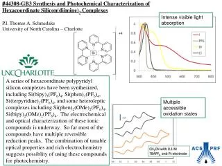
Channel Model The output PSD of a white phosphor-based LED (solid line, which corresponds to the left axis) is compared to the measured spectral reflectance (which corresponds to the right axis) of plaster and plastic wall (dash-dot line), floor (dash line) and ceiling (dot line) 1 1 L Kwonhyung, P Hyuncheol and J R Barry, IEEE Communications Letters, 15, 217–219, 2011.
Channel Model • Multipath effect limits the channel bandwidth • The impulse response of the channel is modeled as a short impulse (caused by LOS path) followed by a broad pulse (multipath effect/NLOS path) • The delay between the two parts is determined by room geometry and size • The NLOS part is usually modeled as a Gaussian pulse
Performance Limits • System is typically either • bandwidth limited • background-light limited (if daylight falls on PD) • If channel-bandwidth limited, use higher-order modulation or equalizer • If background-noise limited: • Shot noise due to receive intensity – nothing can be done • Decrease symbol rate • Channel state information (CSI) is needed at the transmitter
Signal Processing • Optical and electrical filtering: • Block out-of-band background light • Remove electrical harmonics • Equalization required: • Bandwidth limited by LED response and by multipath • Types of equalizers: • FIR filters, adapted using an LMS algorithm • Decision-feedback equalizer • MLSE – very complex • Remove multiuser interference
Challenges and Solutions • As discussed before, main challenges for indoor VLC systems are • Connectivity while moving: users need to be connected when they move inside the indoor environment • Multiuser support: in large areas is vital, many users need to have access to the network at the same time • Dimming: is an important feature in VLC when communications is integrated with lighting • Shadowing: happens when the direct paths from user to all sources are blocked • Some solution has been proposed for each one
Challenges and Solutions • Solution for connectivity • This problem is similar to the connectivity problem in cellular network when you move from one area of the city to another area while speaking with cell-phone • The solution is called “handover”, using which the user is transferred from one BS to another • Handover is done in the area that two BS’s have common coverage • Similar solution can be used in signal processing domain for VLC • The user can be transferred from one light source to another in the area that is under the coverage of both
Challenges and Solutions • Solution for multiuser support • One solution is time division multiplexing (TDM) • Each frame is divided into equal time slots • Each user transmit data in one time slot in a predefined order • The other solution is code division multiple access (CDMA) • Codes are assigned to users • Each user transmit its data using the assigned signature pattern • It is used in 3G and 4G cellular networks • CDMA has been adopted and developed for optical systems • Optical orthogonal codes (OOC) are used as signature pattern for users
Challenges and Solutions • Solution for multiuser support • Last solution is spatial multiplexing • Can use to increase data rate or to add users • Rely on LED arrays and multiple receivers • Or can use an imaging receiver (camera)
Challenges and Solutions • Solution for dimming • Two main solutions are proposed for solving dimming problem in VLC systems • Pulse width modulation (PWM) is combined with other modulation schemes in order to control the duty cycle of the transmitter signal • By controlling the width of the PWM signaling, the dimming level can be controlled • The other solution is using modified forms of PPM • In these schemes multiple pulses are transmitted instead of one pulse • By controlling and changing the ratio between the number of pulses and the length, the dimming level can be altered
Challenges and Solutions • Solution for shadowing • As shown before, the impulse response in VLC systems has two parts • When the line-of-sight (LOS) part (which is received via direct path) is blocked, the impulse response is only the second part • Then the data can be recovered using the second part which is indeed the received data from the indirect paths (multipath signal)