Useful Combinational Basic Blocks in VHDL
690 likes | 1.17k Views
Useful Combinational Basic Blocks in VHDL. This lecture has much material that you should already know. I give it here for those students who may not know and for reference in your projects. Decoders. A decoder is a circuit that converts coded inputs into coded outputs.

Useful Combinational Basic Blocks in VHDL
E N D
Presentation Transcript
Useful Combinational Basic Blocks in VHDL This lecture has much material that you should already know. I give it here for those students who may not know and for reference in your projects.
Decoders • A decoder is a circuit that converts coded inputs into coded outputs. • Usually, the input code has fewer bits than the output code. • The most common decoder is an n-to-2n or binary decoder. • A binary decoder is used when one of 2n outputs needs to be activated based on an n-bit input value.
Decoders in VHDL • There are several ways to write decoders in VHDL. • The most primitive would be to write a structural description equivalent to the logic circuit on previous slide.
Decoders • A 74x139 IC has two independent 2-to-4 decoders.
Decoders • A 74x138 IC has one 3-to-8 decoder.
3 to 8 Decoder in VHDL • The second alternative for a decoder is using the dataflow style.
Decoders • Another alternative is using the behavioral style.
Decoders • Multiple decoders can be used to decode larger code words. • The top decoder (U1) is enabled when N3 is 0, and the bottom decoder (U2) is enabled when N3 is 1. • To handle larger code words, decoders can be cascaded hierarchically.
Decoders • To handle larger code words, decoders can be cascaded hierarchically. • A 5-to-32 decoder can be built with one 2-to-4 and four 3-to-8 decoders. • The 2-to-4 decoder treats the high order bits. • The 3-to-8 decoders treat the low-order bits.
7-segment decoders • A 7-segment display is used in watches, calculators, and devices to show decimal data. • A digit is displayed by illuminating a subset of the 7 line segments. • A 7-segment decoder has a 4-bit BCD as its input and the 7-segment code as its output.
7-Segment Decoders • Exercise 1:Obtain minimised expressions for outputs of the 7-segment decoder. • Exercise 2:Write a VHDL description of a 7-segment decoder.
Encoders • An encoder is a circuit whose output code has normally fewer bits than its input code. • The simplest encoder to build is a 2n-to-n or binary encoder. • It has the opposite function as a binary encoder. • Equations for an 8-to-3 encoder :Y0 = I1 + I3 + I5 + I7Y1 = I2 + I3 + I6 + I7Y2 = I4 + I5 + I6 + I7 • Only 1 input is active at a time. • What happens if 2 inputs are asserted (ex: I2 and I4)?
Encoders • To implement a request encoder, the binary encoder does not work! • It assumes that only 1 input is asserted. • If multiple requests can be made simultaneously, a priority must be assigned to the input lines. • When multiple requests are made, the device (priority encoder) produces the number of the highest-priority requestor.
Encoders • Input I7 has the highest priority. • Outputs A2-A0 contain the number of the highest-priority asserted input, if any. • The IDLE output is asserted if no inputs are asserted. • Intermediate variable Hi is 1, if Ii is the highest priority 1-input:H7 = I7 H6 = I6·I7’H5 = I5·I6’·I7’ H4 = I4·I5’·I6’·I7’... (similar equations for H3-H0) • A0 = H1 + H3 + H5 + H7A1 = H2 + H3 + H6 + H7A2 = H4 + H5 + H6 + H7 • IDLE= I0’·I1’·I2’·I3’·I4’·I5’·I6’·I7’
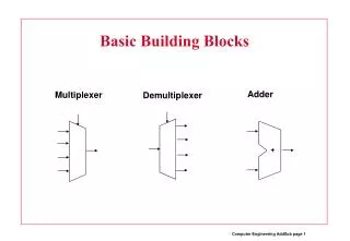
Multiplexers • A multiplexer (mux) is a digital switch. • It connects data from one of n sources to its output. • The SEL input selects among the n sources, so s = log2 n. • When EN=0, Y=0;When EN=1, the mux is working. • Multiplexers are used in computers between the processor’s registers and its ALU, to select among a set of registers which one is connected to the ALU.
Multiplexers • A 74x151 IC has one 8-input, 1-bit multiplexer. • The select inputs are named A,B,C, where C is the MSB. • The enable input EN_L is active low. • Both active-low and high versions of the output are provided
Multiplexers • A 74x157 IC has one 2-input, 4-bit multiplexer. • The select input is S. • The enable input G_L is active low. • The truth table was extended and inputs appear at the outputs columns.
Multiplexers • A multiplexer can be used to select one of n sources of data to transmit on a bus. • At the other end, a demultiplexer can be used to route the bus to one of m destinations. • The function of a multiplexer is the inverse of a demultiplexer’s. • A 1-bit, n-output demultiplexer has one data input and s inputs to select one of the n=2s data outputs.
c a m b Multiplexer with one control
c a m Using case to describe mux
Multiplexers • It is easy to describe multiplexers in VHDL. • In the dataflow style, a SELECT statement is required. There are many variants • Here we use standard logic, when has other arguments and we use others Using standard logic
Multiplexers • In a behavioural architecture, a CASE statement is used. • It is easy to customise the selection criteria in a VHDL multiplexer program. Below are more multiplexer and multiplexer-like circuit descriptions
Behavioral Synthesis of sequential selection instruction using Case
Synthesis of numeric types: integer and real • Types and subtypes which include negative values in their definition are encoded in 2’s complement code • Types and subtypes that include only positive values are binary encoded • Number of bits used depends on the largest allowed value for each object
Synthesis of numeric types: Integer, Real We declare various types of signals res1, res2, res3 • Because of different types of res1, res2, res3, different implementations are build op1 + op2 is 32 bits res1 is 16 bits res2 is 32 bits
Synthesis of enumerative types • Enumerative types are synthesized using binary encoding. First element from left gets value 0. • Number of assigned elements (n) is smallest from possible elements <= 2n • Type bit is synthesized as “wire” • Type character is synthesized as 8 * “wire”
Synthesis of enumerative types declaration Is encoded in synthesis as: 00, 01, 10, 11 User defined encoding uses attributes In general you have to declare type, some tools may understand
Type: std_logic_1164 U encoded by M, X encoded by M, 0 encoded by 0, etc
Synthesis of assignment statements for logic operators m is a vector so this is a bit-by-bit instruction
Synthesis of assignment statements for relational operators m is a boolean so implementation as a predicate
Synthesis of Arithmetic Operators • m is a 3 bit vector so it is implemented as such
Synthesis of “Logic copying instructions” a_0 m_3 a_1 m_2 a_2 m_1 a_3 m_0 a_0 m_2 a_1 m_1 a_2 m_0
First example of Synthesis of “Logic copying instructions” a_0 m_3 a_1 m_2 a_2 m_1 a_3 m_0 a_0 m_2 a_1 m_1 a_2 m_0
Second Example of Synthesis of “Logic copying instructions” a_0 m_3 a_1 m_2 a_2 m_1 a_3 m_0 a_0 m_2 a_1 m_1 a_2 m_0
XOR and Parity Circuits • An Exclusive-OR (XOR) gate is a 2-input gate whose output is 1, if exactly one of its inputs is 1. • An XOR gate produces a 1 output if its input are different. • An Exclusive-NOR (XNOR) is just the opposite: it produces a 1 output if its inputs are the same. • The XOR operation is denoted by the symbol . • X Y = X’·Y + X·Y’
XOR and Parity Circuits • There are 4 symbols for each XOR and XNOR function. • These alternatives are a consequence of the following rule: • Any two signals (inputs or output) of an XOR or XNOR gate may be complemented without changing the resulting logic function. • In bubble-to-bubble design we choose the symbol that is most expressive of the logic function being performed.
XOR and Parity Circuits • n XOR gates may be cascaded to form a circuit with n+1 inputs and a single output. This is a odd-parity circuit, because its output is 1 if an odd number of its inputs are 1. • If the output of either circuit is inverted, we get an even-parity circuit, whose output is 1 if an even number of its inputs are 1.
XOR and Parity Circuits • VHDL provides the primitive operators xor and xnor. • A 3-input XOR device can be specified in VHDL dataflow style program. 3-input XOR
XOR and Parity Circuits • A 9-input parity function can be specified behaviorally.
Comparators • Comparing two binary words is a common operation in computers. • A circuit that compares 2 binary words and indicates whether they are equal is a comparator. • Some comparators interpret their input as signed or unsigned numbers and also indicate an arithmetic relationship (greater or less than) between the words. • These circuits are often called magnitude comparators. • XOR and XNOR gates can be viewed as 1-bit comparators. • The DIFF output is asserted if the inputs are different.
Comparators • The outputs of 4 XOR gates can be ORed to create a 4-bit comparator. • The DIFF output is asserted if any of the input-bit pairs are different. • This circuit can be easily adapted to any number of bits per word.
Comparators • An iterative circuit is a combinational circuit with the following structure. • The circuit contains n identical modules, each of which has both primary inputs and outputs and cascading inputs and outputs. • The left-most cascading inputs are usually connected to fixed values.
Comparators • Two n-bit values X and Y can be compared one bit at a time using a single bit EQi at each step to keep track of whether all of the bit-pairs have been equal so far: • 1. Set EQ0 to 1 and set i to 0.2. If EQi is 1 and Xi=Yi, set EQi+1 to 1. Else set EQi+1 to 0. 3. Increment i.4. If i < n, go to step 2.
Comparators • Several MSI comparators have been developed commercially. • The 74x85 is a 4-bit comparator. • It provides a greater-than output, a less-than output and an equal output. • The 74x85 also has cascading inputs for combining multiple chips to create comparators for more than 4 bits. • AGTBOUT = (A>B) + (A=B) · AGTBINAEQBOUT = (A=B) · AEQBINALTBOUT = (A<B) + (A=B) · ALTBIN
Comparators • With three 74x85 circuits, a 12-bit comparator can be built.
Comparators • VHDL has comparison operators for all of its built-in types. • Equality (=) and inequality (/=) operators apply to all types. • For array and record types, the operands must have equal size and structure, and the operands are compared component by component. • VHDL’s other comparison operators (>, <, >=, <=) apply only to integers, enumerated types and one-dimensional arrays of enumeration or integer types.
Adders, Subtractors and ALUs • Addition is the most commonly performed arithmetic operation in digital systems. • An adder combines two arithmetic operands using the addition rules. • The same addition rules, and hence the same adders, are used for both unsigned and 2’s complement numbers. • An adder can perform subtraction as the addition of the minuend and the complemented subtrahend. • A subtractor can also be built to perform subtraction directly. • An ALU (Arithmetic and Logic Unit) performs addition, subtraction, and other logical operations.
Adders, Subtractors and ALUs • The simplest adder, called a half adder, adds two 1-bit operands X and Y, producing a 2-bit sum. • The sum can range from 0 to 2, which requires two bits to express. • The low-order bit of the sum may be named HS (half sum). • The high-order bit of the sum may be named CO (carry out). • The following equations can be written:HS = X Y = X·Y’ + X’·YCO = X·Y • To add operands with more than one bit, carries between bit positions must be provided.