Download
1 / 16
160 likes | 299 Views
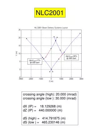
The 2mrad horizontal crossing angle IR layout for the ILC. Rob Appleby Daresbury Laboratory MDI workshop at SLAC - 07/01/05 D. Angal-Kalinin (DL), P. Bambade, B. Mouton (Orsay), O. Napoly, J. Payet (Saclay). Could this be used for the ILC?. Rationale.

E N D
The 2mrad horizontal crossing angle IR layout for the ILC Rob Appleby Daresbury Laboratory MDI workshop at SLAC - 07/01/05 D. Angal-Kalinin (DL), P. Bambade, B. Mouton (Orsay), O. Napoly, J. Payet (Saclay)
Rationale • (cold ILC bunch-spacing no multi-bunch kink instability) • • only ~15% luminosity loss without crab-crossing (2 mrad) • • correction possible without cavities exploiting the natural • ’ in the local chromatic correction scheme used • • no miniature SC final doublet needed • • no strong electrostatic separators needed, and no septum • • both beams only in last QD more freedom in optics • • negligible effects on physics • • spent beam diagnostics may be easier compared to head-on (see CARE/ELAN Document 2004-20)
Possible doublet parameters for 0.5-1 TeV SC QD (r 35mm) 214-228 T/m warm QF (r ~ 10mm) 140-153 T/m 1-1.9m 3m < 2 mrad l*=4.1m ~ 6 mrad 1.3-2.3m optical transfer R22 ~ 2.84 from IP to QD exit to beam diagnostics (consistent with global parameter sets as in TESLA TDR)
LHC NbTi IR quads • gradient for 0.5 TeV : 215 T/m, • radius 35mm (effective = 31mm) • higher gradients are studied for LHC upgrades using NbTi(Ta), Nb3Sn Tolerable beam power losses in SC QD local & integral LHC spec: 0.4 mW/g & 5 W/m US-cold design parameters assumed at IP Ne 2 1010 per bunch x=543(489) nm y=5.7(4) nm z=0.3 mm Ebeam = 250(500) GeV x=15(24.2) mm y=0.4 mm
Beamstrahlung clearance at QF Calculated need of 0.5mrad around beam direction at IP in realistic beam conditions & beam pipe with r = 10mm in QF Horizontal cone half-opening angle Vertical cone half-opening angle CARE/ELAN document 2004-21 (A+B) 0.5 TeV doublet c 1.7mrad 1 TeV doublet c 1.6mrad
Beam power losses in QD without beam size effect with beam size effect withbeam size effect Compton tail Beamstrahlung tail 1 TeV doublet for Ne 2 1010 perbunch 0.5 TeV doublet 0.5 TeV using 1 TeV doublet 1 TeV doublet for Ne 1010 per bunch
Beamstrahlung extraction Simultaneous charged beam and beamstrahlung extraction feasible at 0.5 TeV (2mrad) Harder at 1 TeV - c=1.6mrad seems favoured (benefit from SCQ grad. R+D) incoming, outgoing and beamstrahlung close together at QF plan common beampipe, with separation later
Clearance at QF for synchrotron radiation emitted in QD & QF x,y = core (1-) photons at QF (estimated from CS paras.) (x - c zQF)2 x2 + y2 y2 = 1 need to collimate to nx,yx,y nx,y=5.9, 49 • can increase c • specially shape QF magnet poles • use smaller beam pipe radius If the photon rate reflected off QF and transmitted back to the VD results in too tight collimation requirements (recent work by T. Murayama OK) IP z
Luminosity loss without crab crossing L/L0 ~ 0.85 geometric formula 0.88 c[mrad]
Extraction line for disrupted beam • Transport spent beam with controlled losses, both under disrupted and undisrupted conditions. • Constant geometry up to 1 TeV use 1 TeV doublet design • Diagnostics on disrupted beam • Compton polarimeter (need chicane and zero net bend) • Energy measurement (energy chicane) • WISRD-style spectrometer • image beam Choose 10W in QD, requiring c=1.6mrad Study for 1 TeV machine and Ne=2 1010 (hardest case!) Extraction line geometry fixed: R22c=4.544mrad
Initial achromat to cancel dispersion • Off-axis beam in QD produces horizontally dispersed beam • Initial extraction line achromat designed to cancel this • Horizontally focussing quad QFX produces phase advance QFX very close to incoming beamline (50mm) use current-sheet quadrupole and 8m drift QD->QFX • BPT=1.3T (g=26 T/m) • aperture radius 5cm • l=5.8m (1 TeV) • Designed and costed for TESLA TDR (2001-21)
Initial achromat to cancel dispersion II • Power loss for aperture r=5cm, scaling r • For 1 TeV, lose 3.1kW for =1, 350W for =1.5 and 69kW for =0.5 • Ne=1 1010, lose 10W; 500 GeV 80W (=1) • Use Tungsten collimator need to check VXD backsplash • QFX becomes weaker doublet; reduce over focussing • Achromat completed by 14m drift and 2.5mrad bend • Inherent flexibility - optimise strengths, lengths and apertures r QFX
Linear dispersion for the 1 TeV lattice point-focus and chicane "bend back" achromat
-functions for the 1 TeV lattice point-focus and chicane achromat "bend back"
Some on-going studies • Increase BeamCAL aperture to 2cm to relax collimation? K. Büsser: rate in VXD increases - origin from inside of BeamCal or QD. Reduce by High Z material on BeamCAL and (early) QD surface? • Further study of post-IP beam transport beyond QFX to limit beam losses to acceptable levels and allow post-IP beam instrumentation. Possible reduction using chromatic correction scheme; inclusion of the detailed B field map in the half-quadrupole QFX • Feasibility of collimator for kW power loss for the case of TeV machine - backgrounds in the detector? • Beam dumps? incoming beam to -dump separation 0.62m, -dump to disrupted beam separation 0.54m