Download
1 / 17
180 likes | 359 Views
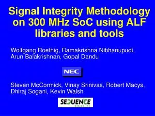
Signal Integrity Methodology on 300 MHz SoC using ALF libraries and tools. Wolfgang Roethig, Ramakrishna Nibhanupudi, Arun Balakrishnan, Gopal Dandu. Steven McCormick, Vinay Srinivas, Robert Macys, Dhiraj Sogani, Kevin Walsh. Introduction.

E N D
Signal Integrity Methodology on 300 MHz SoC using ALF libraries and tools Wolfgang Roethig, Ramakrishna Nibhanupudi, Arun Balakrishnan, Gopal Dandu Steven McCormick, Vinay Srinivas, Robert Macys, Dhiraj Sogani, Kevin Walsh
Introduction • Signal integrity becomes dominant factor for design closure in 180nm technology and below • Conventional design method for SI • multiple point tools for analysis • repair manually or by scripts • New design method for SI • Same tool for analysis and optimization • Unified signal integrity library • Signal integrity library contents using the Advanced Library Format (ALF) will be explained • Results on 333 MHz SoC design will be shown
Conventional crosstalk-aware STA P&R data pessimistic! delay calculation time window calculation pessimistic! SDF Extra delay due toaggressor / victim overlap STA Refine time windows Time windowsaccurate? Timingo.k.? no no yes yes done Do another design iteration
Issues with crosstalk-aware STA • Iterative STA due to Chicken-and-egg problem • To calculate crosstalk-effects on delay, time windows must be known • To calculate time windows, delay must be known • Conventional STA can only handle one time window per clock cycle • Pessimistic assumption for crosstalk • Overestimation of multi-aggressor effects • New crosstalk-aware STA • Delay and noise calculation integrated in STA • Supports multiple activity windows per clock cycle
New STA with activity windows A A Y B B Y One clock cycle • Multiple activity windows per clock cycle • Individual slew rates for each activity window • Reduces timing uncertainty • More accurate calculation of coupling effects on delay and noise
Accurate evaluation of crosstalk effects Aggressor Victim Aggressor Victim # paths No time windows: pessimistic 250 200 150 Min/Max windows: still pessimistic 100 50 Activity windows: accurate - -2.5 -5.0 -7.5 -10.0 -12.5 -15.0 -17.5 -20.0 -22.5 -25.0 -27.5 Crosstalk neglected: optimistic Negative Time Slack Min/Max windows overlap: crosstalk delay is estimated Activity windows do not overlap: no crosstalk delay occurs
Other signal integrity effects • Noise • Crosstalk generates spurious waveforms on supposedly quiet signal lines • May cause unintended flip flop switch • Functional failure • Electromigration • High electrical current inside cells • May break vias, contacts wires • The higher the frequency, the higher the damage Analysis is not enough Prevention and repair must be provided
Conventional Signal Integrity Flow Netlist / floorplanchange netlist floorplan Placement change Timing-driven placement Routing change Routing Extraction Timingo.k.? yes Noiseo.k.? yes no EMo.k.? yes no no done
Issues with conventional SI flow • Trial-and error approach • Multiple point tools do separate SI checks • Crosstalk-aware timing • Noise • Signal electromigration (EM) • No common library • Check and repair is done in different tools • Mutual unawareness of SI effects • Timing repair may cause noise violation • EM repair may cause timing violation • Unpredictable number of design iterations
New signal integrity design flow netlist floorplan Initial placement Pre-route optimization ALF libraryTimingNoiseElectromigration Routing Extraction Post-route optimization done
Accurate timing library .lib ALF Error criterion Average Std deviation Max - Min .lib + 3.9 % +/- 5.0 % 17.4 % ALF + 0.5 % +/- 2.2 % 11.1 % • Tool results with .lib and ALF compared with SPICE ALF is more accurate, less pessimistic than .lib
Timing and noise waveforms Timing waveform@ driving point Timing waveform@ coupling point ALF aggressor Driverresistance victim Noise waveform • Timing waveform shaped by aggressor driver resistance • Noise waveform shaped by victim driver resistance • Accurate characterization of driver resistance is key
Accurate noise modeling ALF output noise peak dynamic noise margin inputpulse width output load cap output load cap static noise margin inputnoise peak inputpulse width • Noise propagation for combinatorial cells • Dynamic noise margin for sequential cells • Greatly reduces pessimistic noise violations
Signal Electromigration B A B A 1 ALF 3 Y 2 Y 4 5 • Conditions for EM damage inside cell represented by abstract vector • Each vector has associated max. frequency 1: (10 A)2: (01 A)3: (01 Y)4: (10 A -> 10 Y)5: (01 B -> 10 Y)
Signal Electromigration Flow • ALF library contains max frequency = f(slew, load) for each EM characterization vector in cell • Global activity file (GAF) contains actual switching frequency for each design instance vector • GAF is generated by event-driven or probabilistic simulation • EM violation, if max frequency < actual frequency • For optimization, EM frequency limit is transformed into max cap. limit = f(slew) for given frequency • After net list change, actual frequency is locally propagated through inserted buffers (ECO GAF)
Design result TechnologyClock frequencyDie sizeHard macrosTotal gate count 130 nm 333MHz, 167MHz et al8.5mm*8.5mm3003.5 M Design dataCell instancesWorst time slack# timing violations# SI violations initial448K-10.7 ns860024 500 final467K0.0 ns00 Design stepAutomatic floor planTotal P&RTotal ExtractionTotal Optimization Runtime2 H20 H16 H24 H
Conclusion • ALF provides comprehensive signal integrity support • Timing, noise, electromigration • ALF enables better crosstalk-aware STA • Accurate ALF timing models eliminate the need for proprietary delay calculators • ALF enables efficient signal integrity flow for ASIC and SoC designs • Iteration-free analysis and optimization • Sign-off quality ALF is the library for next-generation tools