Download
1 / 24
250 likes | 487 Views
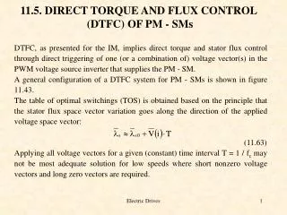
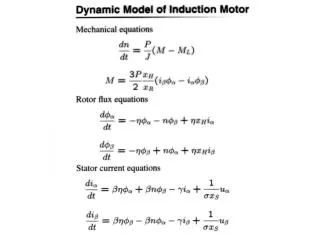
DC/AC Converter Control Torque and Flux Control. Converter circuit + Motor Control design Design sliding surface for torque and flux Lyapunov function. denote. Torque and Flux Control (cont.). Calculate. where. does not depend on control. and. Torque and Flux Control (cont.).

E N D
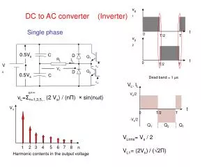
DC/AC Converter ControlTorque and Flux Control • Converter circuit + Motor • Control design • Design sliding surface for torque and flux • Lyapunov function denote
Torque and Flux Control (cont.) • Calculate where does not depend on control and
Torque and Flux Control (cont.) • Select control logic such that Control Logic tends to zero
Torque & Flux Control (approach 2) • Cascade Control • From torque and flux equations: where • Desired can be calculated • Sliding mode to provide desired current
Cascade Sliding Mode Control • Idea: Utilize extra degree of freedom • Sliding surface design
Lyapunov Approach • Select control logic based on Lyapunov function such that sliding mode is enforced • Advantage: simple Control Logic
Decoupling Approach to Enforce Sliding Mode • Idea: to decouple motions in • Method: non-singular transformation: • Advantage: allows frequency analysis performed for each surface individually Control Logic
Vn Control • Objective: optimality by changing • Example: switching frequency reduction
SMPWM Simulation Results • Current tracking and vn tracking
Experimental Setup • Controller: TMS320F2812 DSP • Switching devices: 2MBI100NC-12 IGBT • 3 phase RL load • 50 V DC supply
Experimental Results The first waveforms show the current tracking (and ), the second ones show tracking as a sinusoidal function by the average value of (after filtering out a high frequency component of discontinuous function ).