Download
1 / 18
180 likes | 671 Views
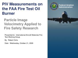
Handbook Chapters 8 and 15 Oil Burner Test for Cargo Liners. Contributors: George Danker – Chairman Ethel Dawson – Accufleet Jim Davis – Accufleet Ingo Weichert – Airbus Hamburg Heinz-Peter Busch – Airbus Bremen Bernd Menken – Airbus Bremen Jean-Francois Petit – Airbus Toulouse

E N D
Handbook Chapters 8 and 15 Oil Burner Test for Cargo Liners Contributors: George Danker – Chairman Ethel Dawson – Accufleet Jim Davis – Accufleet Ingo Weichert – Airbus Hamburg Heinz-Peter Busch – Airbus Bremen Bernd Menken – Airbus Bremen Jean-Francois Petit – Airbus Toulouse Scott Campbell – C&D Aerospace, Huntington Beach Anne Mansuet – CEAT, Toulouse
Areas for Consideration: Section 1: Better definition of burnthrough Section 2: Expanded backside thermocouple locations for thick samples Section 3: Improve and standardize burn apparatus Section 4: Guidance on the mounting and attachment of test specimens Section 5: Guidance on test methodology Section 6: Next steps
Section 1: Better definition of burnthrough 1.1 Flame penetration. Handbook currently defines burnthrough as “Flame penetration of the test specimen”. This is an inadequate definition which permits the development of voids. Flame penetration tends to be directional and geometry alone should not allow for certification. Recommendation: Expand definition of burnthrough to prohibit the development of any void through which a flame may pass. Suggested language: Burnthrough is defined as flame penetration of the test specimen or the development of a visible breach, opening, gap, fissure, or any void through which a flame may penetrate. The development of any such void during the test period shall be cause for failure. FAATC: Concur. Although the suggested language may not be perfect, it is at least more descriptive than the present definition.
Section 1: Better definition of burnthrough 1.2 Panel Shifts / Distortion Recommendation: (All specimens) Panel shifting, twisting or pulling out of the frame creating voids through which flames may pass should be considered a failure. FAATC: Concur. Panels must be mounted using the specified stud and hole arrangement, so any panel that distorts badly enough to pull or twist away from this mounting should be classified a failure. Recommendation: (Cargo liner repair products) Cargo liner patches will occasionally remain in place as a result of being supported only by the upward “pressure” exerted by the test flame. Such patches will fall off immediately with the removal of the test flame. This phenomenon is thought not to be in the spirit of the fire safety and should not be considered a passed test. FAATC: As stated in 8.10.4, “For the patch adhesion test, the patch must be intact after the 5-minute flame exposure”.
Section 1: Better definition of burnthrough 1.3 Backside autoignition / flashover. Autoignition or Flashover is a troubling issue and a very common occurrence: • cold side autoignition of outgases is common, • decomposition byproducts combine with stoichiometric volume of air, • resulting mixture is autoignited by hot surface of underlying panel, • occurs independently of direct flame contact, independently of burnthrough Flashover is currently permitted in Handbook Chapter 8 Supplement 8.10.1. The only stipulation being by implication the specimen which “flashes over” is not relieved from The 400o F maximum backside temperature requirement of Section 8.10.2 Suggested clarification if flashover remains permitted: A “flashover” is permitted only if no breach is present and only if the backside thermocouple temperature does not exceed 400oF
Section 1: Better definition of burnthrough 1.3 Backside autoignition / flashover (con’t) Suggested clarification if flashover is not allowed: Suggested: Any flashover on the cold side of the test panel should be of a small to moderate size and must self-extinguish within a certain period of time. A 15-second limit is proposed. Flashover is important because: • Cargo liner tests are not performed very often – thus an approved material may be • used for years without re-testing, • The “flashover” definition may not cover all phenomena that might occur, • The intent of the cargo liner is to contain a fire – not start another fire. Note on “Wrap around”: Occasionally, the test flame may “wrap around” the test frame and directly ignite backside outgases. This is not considered a failure and baffling (such as sheet metal “skirts”) may be used to block the test flame from direct influence on the backside of specimens.
Section 1: Better definition of burnthrough 1.3 Backside autoignition / flashover (con’t) FAATC: Allow brief (15 second) flashover on back, provided 400oF criteria is not exceeded. Also recommend use of baffle to prevent flashover in situations where this presents a problem.
Section 2: Expanded backside thermocouple locations for thick samples Handbook requires that the backside temperature (NTE 400oF) be taken 4 inches from the backside of the sample. This does not adequately consider materials or structures thicker than a few millimeters. Recommendation: Position thermocouple 4 inches from the frontside of the specimen This now creates problems for thick specimens… One possible approach: Specimen thickness Backside thermocouple location Up to 3 inches 4 inches from the frontside of specimen Greater than 3 inches 1 inch from the backside of specimen FAATC: ??. Current 400oF/4-inch requirement based on input from airframe manufacturers. Are there specimens thicker than 3 inches??
Section 2: Expanded backside thermocouple locations for thick samples For cargo liner design features, a technical note reportedly exists describing that design features should be tested as flat sheets of material in order to respect the specified flame- to-specimen and specimen-to-thermocouple distances. FAATC: As stated in 8.8.8.2, “Test procedures for cargo liner design features are described in FAA Technical Note DOT/FAA/CT-TN88/33 dated September 1988”.
Testing of Cargo Liner Design Features Design Feature Testing Method Lighting Fixtures, Pressure Relief Valves Material that comprises the fire barrier must be tested as a flat sheet, 16- by 24-inch, in either the ceiling or sidewall position.
Testing of Cargo Liner Design Features Design Feature Testing Method Seams, Joints w/Fastening System If seam/joint is found in ceiling liner, it must be tested in ceiling position of test liner, long- itudinally centered over the burner cone. If seam/joint is found in sidewall liner, it must be tested in sidewall position of test liner, in a longitudinal position 2 inches from top of fixture.
Testing of Cargo Liner Design Features Design Feature Testing Method Corner Seam w/Fastening System The liner test frame must be altered to accept the corner system
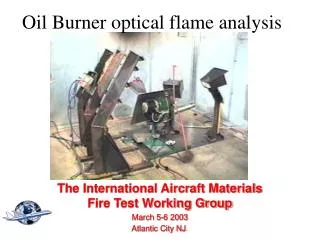
Section 3: Standardize burn apparatus Implement as many of Tim Marker’s oil burner changes as make sense. However, the ultimate arbiter of a proper flame continues to be meeting or exceeding the thermocouple rake temperatures and heat flux density described in Calibration Section 8.7. Temperature across thermocouple rake: >1600oF (>871oC) Heat flux: >7.5 BTU/ft2second (>8.6 w/cm2) Burn apparatus improvements include the use of: Standardized inlet airhose Outboard airflow damper Adjustable (rotating/extensible) nozzle Permissible adjustments include: Minor nozzle variations Fuel pressure adjustments to achieve proper fuel flow rate Rotation of the nozzle Extension or retraction of the nozzle relative to the burner cone Optional tabs, static disc, or stabilizers
Section 3: Standardize burn apparatus FAATC: Will consider RE-placing tolerances on temperature and heat flux (i.e., 1600oF + 100, 7.5 Btu/ft2 second + 0.5), but this very group’s input led to its removal, initially. Implementation of standardized apparatus configuration and improve- ments likely not in the scope at this point.
Section 4: More specific instruction on mounting/attachment of specimens Proposed: Positioning and attachment of test specimens • Considerable latitude is allowed on specimen attachment. • Materials must be tested in a “most severe” orientation. Most vulnerable areas • of test specimen should be exposed to the center of the test flame. FAATC: As per 8.8.8.2, fire barriers are tested as flat sheets, result- ing in uniform exposure to the flame (no “most severe” orientation). Considerable latitude is permitted in method of attaching 16 x 24 test panel to the burn frame, provided: • The attachment of tested feature itself must mimic its attachment in the aircraft. • Design features, in particular, should be tested in an orientation consistent with • their installed geometry. • The burn frame itself should not add reinforcement to any construction that does • not exist as installed in the aircraft. Concur. FAATC: As per 8.8.8.2, design features tested in most severe orientation (longitudinal, centered over flame). Add more description to ensure design feature is tested as installed.
Section 5: Test Methodology Operational recommendations: • Dimensions for the Specimen Retaining Frame needs to be increased at least ¼”. It • can not be the same size as the test specimen. Why? • Standardize fuel to Jet A. Why? • Instead of moving the burner into position to begin test, move the test sample to the burner. • Currently acceptable practice. • Measure air flow at air source and not at burner. Changes dynamics of air flow • Use clamping-locking sample holders instead of bolts. This will allow samples to twist • and pull away from frame more easily • Modify sample holder for testing corner joints. Remove inner corner angle iron between • horizontal and vertical test joint. Currently described in Tech Note. Pre-test warmup: Two minute warm up before test is unnecessarily long and introduces problems. Carbon builds up in cone and can overheat test chamber environment. Recommendation: Reduce 2 minute warm up to 30 seconds. Non concur, 2 minute warm -up necessary to reach steady state conditions.
Section 6: Next steps • Need guidance on recommendations of a “regulatory” nature – most notably Flashover • Need consensus agreement on test methodology recommendations • Develop language and incorporate into appropriate sections of Chapters 8 and 15