Download
1 / 18
190 likes | 534 Views
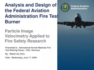
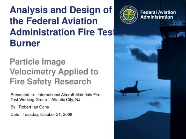
PIV Measurements on the FAA Fire Test Oil Burner. Particle Image Velocimetry Applied to Fire Safety Research. Outline. Motivation Objectives of Study Acquired Data Summary and Future Work. Motivation.

E N D
PIV Measurements on the FAA Fire Test Oil Burner Particle Image Velocimetry Applied to Fire Safety Research
Outline • Motivation • Objectives of Study • Acquired Data • Summary and Future Work
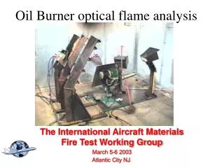
Motivation • The FAA specifies a modified oil burner to simulate the effects of an external fuel fire on an aircraft fuselage and interior components • The specified burner is a typical home heating oil burner • Burner fueled by Jet-A • Burner flame characteristics scaled directly from measurements made from full scale pool fire testing • Heat flux • Temperature • Material performance • Difficulty with achieving calibration and inconsistency of burner performance worldwide has led to the need for a more in-depth, fundamental physical understanding of the thermo-fluidic processes • The objectives of this study are: • Determine the key parameters that affect burner performance • Study parameters individually • Study interactions of parameters • Increase burner consistency and reproducibility • Develop new internal components based upon what is learned • New components will have higher tolerances than original components
Particle Image Velocimetry • Particle Image Velocimetry (PIV) • Fluid flow measurement technique • Measures the displacement of small particles entrained in the flow over a short period of time and calculates the velocity at discrete points • Key Advantages • Non-intrusive measurement of flow • Whole-field measurement; can resolve wide range of flow field areas (µm2 →m2) *From www.dantecdynamics.com
Can PIV Be Used to Study Flow Properties of the Fire Test Burner? • PIV was chosen for this research due to it’s whole-field, non-intrusive flow measurement capability • The burner can be divided into different studies: • Fuel Spray • Swirling Jet Flow • Combined Fuel Spray / Air Flow • Burner Flame • Combustion presents many technical challenges for PIV • High temperatures • Broadband, intense flame luminosity • Intense thermal radiation • Combustion products hazardous to health and equipment
Future Measurements - Spray • Study various spray properties • Effect of viscosity on velocity field (vary fuel temperature) • Obtain sizing information in less dense regions of spray, study effect of viscosity (temperature) on droplet size • Study nozzles for uniformity of spray pattern by rotating measurement plane
Analysis • The effect of the turbulator is apparent in the flow field measurements • The magnitude of the in-plane velocity on the periphery of the flow field is significantly reduced by the action of the turbulator, from ~4 m/s to ~1 m/s • The regions of high velocity on the edges of the flow are compressed into the central region of the flow by the turbulator • This centralized high rotation region is intended to interact with the high mass, high momentum fuel droplets in the spray cone
Future Measurements • Make similar iterative measurements at locations downstream • Study behavior of swirling air flow as a function of axial location (stereo-PIV) • This may give insight into optimal location, orientation of stator and turbulator • Perform same measurements, study effect of variables • Various Re • Fuel spray as seeding, study interaction of airflow on fuel spray
Acquired Images – Reacting Flow Single Camera Nd:YAG Laser Parallel Plane Camera Measurement Plane Frame 1 Frame 2 Measurement Plane Nd:YAG Laser Frame 1 Frame 2 Camera Normal Plane
Nd:YAG Laser Measurement Plane Nd:YAG Laser Measurement Plane 2 Cameras + Beamsplitter 2 Cameras + Beamsplitter PIV Setup –2 Cameras
Non-Reacting Flow Reacting Flow Experimental Setup Burner Settings PIV Settings
Non-Reacting Flow Reacting Flow Comparison: Non-reacting vs. Reacting Flow
Summary • PIV can be used to analyze the various components of the FAA Fire Test Burner • Preliminary measurements were made of the swirling burner exit air flow and spray nozzle flow • A dual camera and beam splitter arrangement was used to perform PIV measurements in a highly sooting, turbulent burner flame • Future Work • Perform independent and combined analyses of spray flow and burner air flow • Determine effect of variations in air and fuel flow on mean flame velocity • Investigate different swirl methods and spray nozzles to develop a next-generation burner that provides more consistent, reproducible results