Identifying Components and Patterns Using The N 2 Chart to Refine Compositional Structure
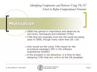
Identifying Components and Patterns Using The N 2 Chart to Refine Compositional Structure. Motivation. CBSE has gained in importance and deserves its own tools, techniques and methods (T/Ms) T/Ms that are originally from the OO world are being used in CBSE, though many claim that CB OO.

Identifying Components and Patterns Using The N 2 Chart to Refine Compositional Structure
E N D
Presentation Transcript
Identifying Components and Patterns Using The N2 Chart to Refine Compositional Structure Motivation CBSE has gained in importance and deserves its own tools, techniques and methods (T/Ms) T/Ms that are originally from the OO world are being used in CBSE, though many claim that CB OO • How would we like using T/Ms meant for the procedural paradigm (PP) in OO software engineering (OOSE)? • If the prospect is not attractive, it is time to start designing T/Ms that are native to the CB paradigm
Mereology: A philosophical/foundational view that studies the world in terms of parts that make up a whole. The Goal The goal is to improve Component-Based Software Engineering (CBSE) process & product quality by understanding the nature of components and component-based systems, and applying this understanding to devising tools, techniques and methods (T/Ms) that facilitate CBSE or any phase/activity of CBSE We aim at facilitating design-level reasoning in CBSE using the N2 Chart – a diagrammatic modeling language (DML) that is “native” to the CB paradigm NATIVE to CB Mereological
Related Work Diagrammatics – especially diagrammatic reasoning (Kulpa 1994) Cognitively informed modeling, f. ex. Gurr, C. and K. Tourlas: “On the Design and Use of Diagrams” in Software Engineering in ICSE 2000, the 22nd International Conference on Software Engineering, 2000. Limeric, Ireland: ACM Press. p. 509-518. NOTE: Not cited in paper! Linguistic pragmatics (not cited in the paper, but used by Gurr-Tourlas and many others) The N2 Chart (Lano 1977, originally from TRW) CBSE, UML
DMLs in CBSE:UML V1.5 #1 Practically all diagrammatic modeling languages (DMLs) used in CBSE are UML-based today • UML V1.5 implementation level component (standard)
UML V1.5 component notation including component specification (can be used at design-level). DMLs in CBSE:UML V1.5 #2 Note that all three classes make up the single component. • Technology platform specific (reminds EJB-style components, see next slide).
DMLs in CBSE:UML V1.5 #3 Technology platform (EJB) specific component notation used elsewhere (popular, see [4], [6], [10]). • Also implementation-bound • Not cited in the paper
DMLs in CBSE:UML V1.5 #4 • Assumes specific programming-language constructs for value and control flow: • Event • Assignment Catalysis. See [7].
DMLs in CBSE:UML V2.0 #5 Single symbol for single design/specification level decomposable component. Finally!
DMLs in CBSE comments We see a move from OO to CB notation in UML This is notably due to a need for addressing design/specification level components in a platform independent manner, This is admittedly also because SDL founders (mostly through Ericsson) are amongst the authors of the major UML 2.0 proposals to OMG The fact that components are addressed and the way they are addressed (not only at implementation level but also at design/specification level) is nevertheless important
RULE 1: Construct NxN matrix with N components on the diagonal RULE 2: Interface from CX to CY is one-way and in the off-diagonal cell (X, Y) RULE 3: All inputs to a component are on its column RULE 4: All outputs from a component are on its row DMLs in CBSE N2 Chart(Lano, 1977, TRW) The N2 Chart is native to CBSE (used in systems engineering). Matrix and node notations are: • LAYOUT is party of the rules! • Designed to facilitate design reasoning!
A DML that is native to CBSE.Designed to facilitate design-level reasoning The N2 Chart: Advantages • ALSO facilitates reasoning about (not included in paper): • Distribution schemes • Cyclic dependencies • Etc. Facilitates identifying critical component and tightly coupled components
The N2 Chart can help identify the “correct” components that make up the target system through refining an initial set of components The RefinementProcess Step 1. Identify candidate components. Use (for example) Abbott’s text analysis approach to identify objects, but look for things that perform – for example by looking at things responsible for actions in “doing verbs” and “transitive verbs”. Step 2. Draw an initial N2 Chart. Step 3. Refine by reducing tightly coupled group of components to single components. Step 4. Rearrange as needed. Step 5. Fully reduced, the design may contain a design pattern. • In step 3 many other concerns will have to be taken into accountin whether to reduce or not.
Notice the change in the kind of com-ponents iden-tified in the three passes • Organizer, provider, participant, invitation, calendar, reservation resources (rooms, catering etc) • Invitation manager, reservation manager, resource manager, calendar manager, reservation • Conference (the whole conference), conference center portal (i.e., the CCP itself), and booking (confirming/finalizing reservation) A Conference Center Portal example: helps participants register to conferences, organizers publicize, organize and mediate conferences, and providers offer and manage their services.It summarizes many aspects of a number of application types. Example Step #1 Using brain-storming (and use-cases to a lesser degree, no Abbott-style text analysis) candidate components are found in 3 passes, each time re-evaluating whether the list is complete or not:
The initial N2 Chart (abstracted). Example Step #2 Notice tightly-coupled groups of components • Note that reducing C7 and C8 is a decision that has to take into account other concerns • Note that there should be three sets of inputs and outputs. Only one (user’s) is taken into account
Reduction table RED. 1 C[2] C2, C3, C4 RED. 2 C[7] C7, C8 RED. 3 i[2]-1 i2-1 and i3-1 The N2 Chart after 1st set of reductions. Example Step #3
The N2 Chart after 2nd set of reductions and a rearrangement. Example Steps #3 and 4
The CB design pattern candidate (including all sets of inputs/outputs). Example Step 5 This is a CB design-pattern candidate It indicates a need for a component that manages the needs of the end-users, another that manages the needs of the mediators, and a third that manages the needs of the providers
Quality is never independent of how well the software engineering “tools” are, how well the toolmakers understand the nature of software engineering and its needs, and how well the software engineers master these “tools”. Conclusions #1 The DML presented (based upon a somewhat modified version of the N2 Chart) is a very simple DML but is nevertheless capable of facilitating design-level reasoning The claim is that this is possible because the N2 Chart is native to the CBSE (i.e., is mereological): it represents what needs to be represented This translates to a “tool that matches its paradigm”: match between the world delineated by the paradigm and its representation (also conceptual manipulation) This stance assumes that choice of a paradigm (in modeling) dictates “what we choose to see and how we choose to see it”
A single paradigm should not be a religion that dictates all aspects and phases of all types of software development. Conclusions #2 Alistair Cockburn’s “Crystal” categorizes software engineering projects, and which types of software engineering projects lend themselves to which types of software development methods Similarly, a paradigm should be chosen with respect to the type of software and with respect to the phase or activity within the development project Component-based software development, at the design phase and in specification-related activities, needs tools that facilitates upon design-level reasoning The same tool(s) may not be effective in other phases of development or in projects other than CBSE projects