Download
1 / 54
610 likes | 1.16k Views
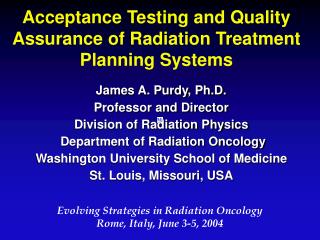
Acceptance Testing and Quality Assurance of Radiation Treatment Planning Systems. James A. Purdy, Ph.D. Professor and Director Division of Radiation Physics Department of Radiation Oncology Washington University School of Medicine St. Louis, Missouri, USA.

E N D
Acceptance Testing and Quality Assurance of Radiation Treatment Planning Systems James A. Purdy, Ph.D. Professor and Director Division of Radiation Physics Department of Radiation Oncology Washington University School of Medicine St. Louis, Missouri, USA Evolving Strategies in Radiation Oncology Rome, Italy,June 3-5, 2004
Acceptance Testing and QA of Treatment Planning Systems • Treatment planning and delivery of radiation therapy are undergoing significant change with continuous advancements in computer hardware computational power and computer graphics. • Image-based 3D planning including IMRT inverse planning is driving a complete shift in the paradigm for the treatment-planning process. • Can be very large difference in functional capabilities and clinical utilization of planning systems. • Acceptance testing and commissioning of planning system is quite complex and may vary from institution to institution.
Acceptance Testing and QA of Treatment Planning Systems • Basic Components • computer workstation • input and output devices for graphics and images • Complex parts of a planning system are • dose-calculation algorithm code • programs used to manipulate 3D graphic displays of the patient, beam geometry, and dose • optimization engine
Acceptance Testing and QA of Treatment Planning Systems • Testing all components of a treatment-planning process can be a formidable task. • Physicist must ascertain extent and complexity of treatment-planning needs of clinic • Based on this information, physicist must establish elements of acceptance, commissioning, and QA of the 3D RTP system.
Acceptance Testing and QA of Treatment Planning Systems • Van Dyk et al.: Commissioning and QA of Treatment Planning Computers. IJROBP 26, 261-273, 1993
Acceptance Testing and QA of Treatment Planning Systems • AAPM Task Group 40: Comprehensive QA for Radiation Oncology. Med. Phy. 21, 581-618 (1994)
Acceptance Testing and QA of Treatment Planning Systems • AAPM Task Group 53: Quality Assurance for Clinical Radiotherapy Treatment Planning. Med. Phy. 25, 1773-1829 (1998)
Acceptance Testing and QA of Treatment Planning Systems • Guidance document on delivery, treatment planning, and clinical implementation of IMRT: Report of the IMRT subcommittee of the AAPM Radiation Therapy Committee. IMRT CWG. Med. Phys., 30(8):2089-2115, 2003.
Acceptance Testing and QA of Treatment Planning Systems • QA program must consider how RTP system is used as well as how it interacts with the treatment planning process. • Creation of a treatment planning process that incorporates self-consistency and procedural checks is a major component of a QA program for treatment planning.
Acceptance Testing and QA of Treatment Planning Systems • Physicist must be afforded adequate time to ascertain extent and complexity of treatment planning needs of radiation oncology clinic. • Based upon this information, physicist must design and implement an appropriate QA program. • For a treatment planning process of a given complexity, QA requirements in a small radiation oncology facility should be no less than those in a large, academic medical center.
Acceptance Testing and QA of Treatment Planning Systems • Acceptance test • performed to confirm that the RTP system performs according to its specifications. • If there is little rigor in the specifications of the RTP system, then there will be little need to design an acceptance test.
Acceptance Testing and QA of Treatment Planning Systems • AT specification divided into 3 categories: • Computer hardware: Includes CPU and all peripheral devices that are part of RTP system, such as display monitor(s), printer, plotter, etc. • Software features and functions: Many software feature specifications will be of the yes/no or exists/does-not exist type, rather than quantitative. • Benchmark tests: Performance on benchmark tests indicates accuracy of dose calculation algorithm under very specific circumstances with specific beam data. Calculation times can also be measured.
Acceptance Testing and QA of Treatment Planning Systems • Test procedures document should be written that clearly describes individual procedures in detail. • Order of tests important to minimize total work necessary and to correlate optimally with other tests. • Procedures to be used must be agreed to by both the user and the vendor. • Acceptance testing should be carried out on the system after it has been installed in the clinic but before it is used clinically.
Acceptance Testing and QA of Treatment Planning Systems • Significant time may be required to perform detailed benchmark testing of dose calculation algorithm accuracy. • Most tests of the hardware and the software features should be performed by the user. • If some tests are performed by vendor, user may want to repeat some or all of the tests to verify results. • Results from acceptance testing should be carefully documented, along with any variation from defined procedures, and kept as long as RTP system is used in the department.
Acceptance Testing and QA of Treatment Planning Systems • Modern RTP process includes many aspects not directly related to dose calculations. • RTP QA program must also handle these important non-dosimetric issues. • Non-dosimetric issues apply to 2-D systems and 3-D planning systems.
Acceptance Testing and QA of RTPS: Image Input Tests • Image Geometry: Document and verify parameters used to determine geometric description of each image (e.g., number of pixels, pixel size, slice thickness) • Geometric Location and Orientation of scan: Document and verify parameters used to determine geometric location of each image (i.e., left- right and head-foot orientations.
Acceptance Testing and QA of RTPS: Image Input Tests • Text Information: Verify that all text information is correctly transferred • Incorrect name or scan sequence identification could cause misuse or misinterpretation of scans. • Imaging Data: Verify accuracy of grayscale values, particularly for conversion of CT number to electron density. • Wrong grayscale data may cause incorrect identification of anatomy or incorrect density corrections.
Acceptance Testing and QA of RTPS: Image Input Tests • Image Unwarping (Removing Distortions): Test all features, including the documentation tools which assure that the original and modified images are correctly identified within the system. • Methodologies which modify imaging information may leave incorrect data in place.
Acceptance Testing and QA of RTPS: Contour Tests • Manual contour acquisition • Digitization process (hardware & software) • Contouring on 2-D images • Autotracking contours • Bifurcated structures • Contours on projection images (DRRs, BEVs) • Contours on CT scannograms • Extracting contours from surfaces
Acceptance Testing and QA of RTPS: Image Use and Display Tests • Verify functionality of window and level setting. • Determine whether displayed window/level values agree with those on scanner/film. • Verify accuracy of the geometric location of the image. • Verify accuracy of the grayscale reconstruction and of any interpolation performed during that reconstruction. • Check consistency between new images and original images. • Verify the capability to remove unwanted imaging information, such as the patient support table.
Acceptance Testing and QA of RTPS: Image Use and Display Tests • Verify accuracy of the geometrical location of the slices with respect to the rest of the patient anatomy. • Verify mean, minimum and maximum CT number inside a region of interest (slice and volume) for a range of situations.
Acceptance Testing and QA of RTPS: Image Use and Display Tests • Verify point coordinates, distances and angles in each coordinate system for each display type. • Confirm color and other rendering functions. • Verify that each panel of a multiple window is kept current as the planning session proceeds.
Acceptance Testing and QA of RTPS: Beam Description/Configuration Tests • Verify that all beam technique functions work, using a standard beam description provided by the vendor. • Verify that library of available machines and beams is correct. • Verify that availability of machine and beam-specific accessories, such as electron cones or wedge is correct.
Acceptance Testing and QA of RTPS: Beam Description/Configuration Tests • Verify correct use and display of user- defined beam names and numbers. • Verify correct use and display of angle readouts for gantry, collimator, and table. • Verify correct use and display of linear motion readouts of table, collimator jaws, and MLC. • Check readout names and motion limitations.
Acceptance Testing and QA of RTPS: Beam Description/Configuration Tests • Verify correct functionality of tools such as those to move isocenters or set SSDs. • Verify correct wedge characterizations (coding, directions, field size limitations,and availability). • Verify correct use and display of compensators.
Acceptance Testing and QA of RTPS: Beam Geometry Display Tests • BEV/DRR Displays • Verify projection of contours/structures defined on axial slices into BEV-type displays. (Compare with the grayscale images for DRR displays. This is most easily done with a simple phantom containing only a few internal structures). • Verify projection of divergent beam and aperture edges. • Check at several different SSDs and projection distances.
Acceptance Testing and QA of RTPS: Beam Geometry Display Tests • Beam Display: Verify that • Positions and field sizes are correct. • Wedges are shown and the orientation is correct. • Beam edges and apertures are shown correctly. • Patient and Beam Labels • Verify patient orientation with respect to beam and orientation annotations. • Verify correctness of orientations and annotations for machine position views or icons associated with 2-D or 3-D displays.
Acceptance Testing and QA of RTPS: Field Shape Design Tests • Verify that system distinguishes between "island" blocks, in which aperture delineates block shape, and"aperture" or "conformal" blocks, for which the drawn aperture encloses the open irradiated area. • Verify correct specification of transmission or block thickness for full blocks and partial transmission blocks. • Test methods used to fit MLC leaves to field shape. • Verify availability/size of electron applicators. • Check all output showing beam apertures used for beam aperture fabrication (e.g., MLC leaf positions, BEV plots).
Acceptance Testing and QA of RTPS: Wedge Tests • Confirm that wedge orientation and angle specifications are consistent throughout RTP system, including hardcopy output. (If possible, they should agree with treatment machine conventions). • Check display of wedges in different 2D planes for different beam directions, coll. rotations, wedge orientations. • Check display of wedges in room view 3D displays for situations described above. • Verify that wedge orientations and field sizes not allowed by treatment machine (energy) are not allowed in RTP system.
Acceptance Testing and QA of RTPS: Wedge Tests • Autowedges (wedges inside the head of the machine) : Confirm that the division of a field into fractional open and wedged fields agrees in the RTP system and on the treatment machine. • Dynamic wedge. Verify that the implementation in the RTP system has the same capabilities, limitations, orientations and naming conventions as on the treatment machine.
Acceptance Testing and QA of RTPS: Dose Calculation Tests • Verifies that dose calculation program correctly computes doses with respect to algorithm used • Documents limitations of algorithm and its’ implementation • Reviews all input data for all radiation sources for consistency and validity • Provides information required to guide treatment decisions based on documented algorithm limitations
Acceptance Testing and QA of RTPS: Dose Calculation Tests • Photon Beam DoseCalculations: Perform dose calculations for a standard photon beam dataset. Tests should include: • various open fields • different SSDs • blocked fields • asymmetric jaw fields • MLC-shaped fields • wedged fields • inhomogeneity test cases • multi-beam plans • other tests
Acceptance Testing and QA of RTPS: Dose Calculation Tests • Electron Beam Dose Calculations: Perform a set of dose calculations for a standard electron beam dataset. Tests should include: • open fields • different SSDs • shaped fields • surface irregularities • inhomogeneity test cases • other tests
Acceptance Testing and QA of RTPS: Dose Calculation Tests • Brachytherapy Dose Calculations: Perform dose calculations for single sources of each type, as well as several multi-source implant calculations. Tests examples include: • standard implant techniques such as a GYN insertion with tandem and ovoids • two-plane breast implant • prostate seed implant
Acceptance Testing and QA of RTPS: Dose Display Tests • Dose Points: Verify that • point is defined at the desired 3-D coordinates. • point is displayed at the correct 3-D position. • dose at point is displayed correctly. • Interactive Point Doses: Verify that • point coordinates correctly correspond to cursor position on display. • dose at point is displayed correctly. • Consistency: Verify that • doses in intersecting planes are consistent. • different dose display techniques are consistent.
Acceptance Testing and QA of RTPS: MLCs - Dose within the Field Tests • Leakage through leaf (~2%) • Between neighboring leaves (~5%) • At abutting leaf pairs (15% or higher if rounded ends)
Acceptance Testing and QA of RTPS: MLCs - Dose within the Field Tests • MLCs must be very accurate for subfields to add together properly
Segment 1 Segment 2 Segment 3 Segment 4 Leaf Positioning and Gap Width • Dose delivered with IMRT is very sensitive to errors in the calibration of leaf position
1) Displacement of both leaves 2) Overtravel of Left leaf 3) Overtravel of Right leaf Leaf Calibration and Film Test
Acceptance Testing and QA of RTPS: Dose Display Tests • Dose Grids:Verify • Dose is correctly interpolated between grid points for both small and large spacing. • 2-D Dose Displays: Verify • Isodose lines (IDLs) are correctly located. • Colorwash display lines up correctly with IDLs and agrees with point dose displays.
Acceptance Testing and QA of RTPS: Dose Display Tests • Isodose Surfaces: Verify • Surfaces are displayed correctly. • Surfaces are consistent with isodose lines on planes.
Acceptance Testing and QA of RTPS:IMRT Commissioning • All tests that are required to verify a 3D-TPS • TG-53 requirements • Accurate beam data is essential IMRT modeling • Penumbra model is extremely critical • Small field output factors are required • Combination of micro-chambers, diodes and film may be used • Film, TLD, MOSFET, diode and Ion-chamber dosimetry are used for commissioning tests
Acceptance Testing and QA of RTPS:IMRT Commissioning • MLC leaf positioning accuracy • Better than a millimeter • MLC leaf end location • Gap width • Beam characteristics for small MUs • Dose/MU constancy • Flatness and symmetry of the beam • Leaf speed accuracy
Acceptance Testing and QA of RTPS: IMRT Commissioning - Plane Film Analysis Plain Field 3 Plain Field 1 • RTPS applies the planned fluence on a solid water phantom at a known depth • Computes the dose at that depth and generates a dose map file • Expose a film – Convert OD to dose • Compare with dose map generated by RTPS
Acceptance Testing and QA of RTPS: IMRT Commissioning - Total Plan Validation • Transfer the patient plan to a phantom • Treat the phantom and measure the doses • Ion-chambers, Films, MOSFET dosimeters • Compare the doses generated by the TPS
GTV (target) Normal Structure PTV (target) Acceptance Testing and QA of RTPS: Dose-Volume Histogram Tests • Structure Identification • Test Boolean combinations of objects (VROI and DVH Normal Tissue - Target), and how voxels which belong to multiple structures are handled.
Acceptance Testing and QA of RTPS: Dose-Volume Histogram Tests • Histogram Bins and Limits • Verify appropriate histogram bins and limits are used. • DVH Calculation • Test DVH calculation algorithm with known dose distributions. • DVH Types • Verify that differential, and cumulative type of DVH are calculated/displayed correctly. • DVH Plotting/Output • Test DVH plotting/output using known dose distributions.
Unspec. Tissue Int Struct Int Struct TV1 TV1 TV3 TV3 TV2 TV2 Unspec. Tissue Acceptance Testing and QA of RTPS: Dose-Volume Histogram Tests • Dose Display, Dose-Volume Histograms User-created volumes/dose distributions may also be used for additional tests.
Acceptance Testing and QA of RTPS: Multiple Beam Dose Distributions Tests • Multiple beam dose distribution summation (and subtraction - deletion) • Arc beam simulation and verification (for algorithms which use static field superposition) • Spot check isodose plots and display using point dose samples and comparing to overlying curves
Acceptance Testing and QA of RTPS: Hardcopy Output Tests • Hardcopy Output Print out all hardcopy documentation for a given series of plans, and confirm that all textual and graphical information is output correctly.