Walchem W100 Controller: Flexible Performance with Large LCD Display
110 likes | 147 Views
The Walchem W100 controller offers a universal platform for flexibility and performance. Its large custom display shows alarms, user-defined fields, and menu items with symbol-based icons for easy navigation. Features include user-defined inputs and outputs, various sensor options, relay outputs, digital inputs, and more. The intuitive menu system and tactile keypad make operation straightforward. This overview covers the controller's functions, from inputs to outputs and configurations, with helpful tips and FAQs provided. Discover the versatility of the Walchem W100 controller for efficient monitoring and control.

Walchem W100 Controller: Flexible Performance with Large LCD Display
E N D
Presentation Transcript
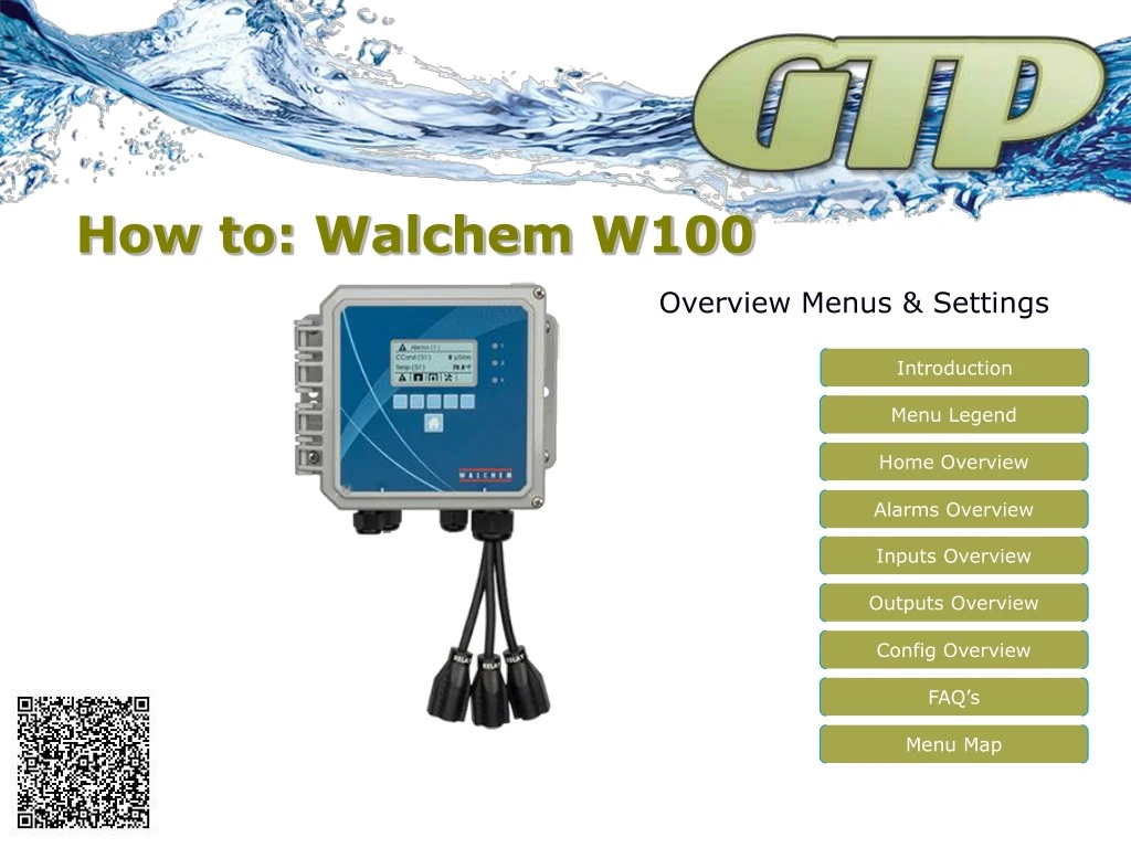
How to: Walchem W100 Overview Menus & Settings Introduction Menu Legend Home Overview Alarms Overview Inputs Overview Outputs Overview Config Overview FAQ’s Menu Map
Introduction Large Custom LCD Display Walchem W100 controller designed on a universal platform for flexibility and performance. Large custom display shows alarms, user defined fields and menu items. Custom symbol based menu icons help guide you through settings and screens with ease. Features: Large custom display User defined inputs & outputs Single sensor input Contacting & Electrodeless Cond Sensors pH or ORP Sensors Disinfection Sensors Three user defined relay outputs 115VAC or Dry Relays Pulse Proportional Relays Twox user defined digital inputs Flowswitch, Water Meter or Flow Sensor Optional 4-20mA outputs Relay Indicators Tactile Keypad 3 User Defined Relay Outputs Sensor & Digital Inputs
Menu Legend The universal platform of the W100 controller sometimes allow for more than what was bargained for. With complete flexibility, sometime the simple task(s) get lost. Let go over the basics. Icon Based Menu Systems. In the legend to the right, you can see the basics for their menu system. Keep these in mind as we go through this training session. Tips: When you get lost or turned around, home button gets you directly back to the start When you see the maintenance button, press it. Viewing settings is mostly a waste of time, press the button so you can change something you need to.
Home Overview Home Screen: The home screen is user definable (so yours may look different) and will show you up to 2 settings and top of screen is devoted to alarm(s) conditions. Symbols across the bottom will navigate you through set up and maintenance. From left to right, we should see the alarm symbol, inputs symbol (up), outputs symbol (down) and the maintenance symbol. Let’s go to through each choice, and what is available. Use the home button on bottom to came back to here.
Alarms Overview Alarms Menu: Will detail out what current alarms are on the controller. Use the indicators to figure where to go to correct condition Example: Flowswitch (D1) would be in the digital inputs menu, digital input #1. Use the up and down arrow keys, if there are more than two alarms. Refer to the manual for details or contact us for help. See FAQ section at the end of this presentation for guidance to common sections of the controller.
Inputs Overview Inputs Menu: The inputs screen will allow you to set-up, maintain and define all items that talk to the controller. Such as: Sensors Inputs (S_) : Conductivity, pH, ORP and Disinfection Digital Inputs (D_) : Flow switches, Level Switches, Flow meters and Flow Sensors Using the up and down arrow keys, highlight the input you need to edit and press the enter key on the right. Refer to the manual for details or contact us for help. See FAQ section at the end of this presentation for guidance to common sections of the controller.
Output Overview Output Menu: The outputs screen will allow you to set-up, maintain and define all items that being controlled by the controller. Such as: Control Relays (R_) : Either powered, pulsing or dry control relays for valves, pumps, BMS systems or alarms Analog Output (A1) : 4-20 mA output for chart recorders, pumps, BMS systems or control valves. Using the up and down arrow keys, highlight the output you need to edit and press the enter key on the right. Refer to the manual for details or contact us for help. See FAQ section at the end of this presentation for guidance to common sections of the controller.
Config Overview Config Menu: This menu is to setup units of measure, times and date, controller name, export/import files, datalogs and board status. Menu items are: Global Settings Security Settings Display Settings File Utilities Controller Details Using the up and down arrow keys, highlight the setting you need to edit and press the enter key on the right. Refer to the manual for details or contact us for help. See FAQ section at the end of this presentation for guidance to common sections of the controller.
This overview should answer a few questions. The upper right is the MAIN menu. Dash lines lead from buttons and symbol legend defines icons. A larger PDF version is available on our website.
FAQ’s Sensor Calibration: This will be in the inputs menu, pan to and press sensor to calibrate, press the crosshair symbol. Change/Configure Blowdown: This will be in the output menu. Pan to and press the relay you want to use for blowdown, press maintenance button, make sure relay in the in proper mode by panning to bottom of listing (should be on/off set point), change set point and Deadband as needed. Change/Configure Feed: This will be in the output menu. Pan to and press the relay you want to use for feed, press maintenance, and pan to the bottom of list to make sure relay is in the proper mode. Popular choices are feed & bleed, feed then bleed or flow timer. Relay is programmed but does not come on: Make sure the relay is in the auto mode, if so, make sure it is not interlocked with something it should not be. Controller still bleeds when no flow: Make sure interlock is set with Flowswitch. I cannot calibrate the controller: Make sure proper sensor is chosen and when used, the temperature portion of that sensor is properly set up. For safety reasons the controller will only allow the controller to modify what it thinks it is (raw value) 1.5 times. After that the sensor should be replaced. Which Calibration should I use: There are a few, and depending on the application you should use the most effective. Basic applications that are not regulated or inspected can use the one point process or one point buffer mostly. Two point buffer is best for more stringent application and should always be use on pH/ORP installation. This will provide a slope. Disinfection will have two types of calibration, buffer and a zero calc. Best to do both. When changing/replacing sensors please, start fresh and reset calibration values. Contact us for further help.
Contact Us Mailing Address: General Treatment Products P.O. Box 8697 Brea, CA 92822-5697 Shipping Address: General Treatment Products 113 Viking Ave. Brea, CA 92821 Phone: 714) 257-9165 FAX: 714) 257-9215 Internet:http://www.gtpcompany.com E-Mail:customerservice@gtpcompany.com


