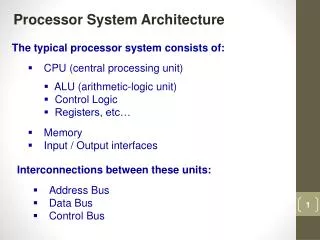
Embedded Processor Architecture 5kk73
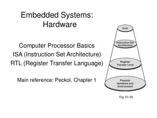
RISC Instruction Set Implementation Alternatives == using MIPS as example ==. Embedded Processor Architecture 5kk73. TU /e 5kk73 Henk Corporaal 2014. Topics. MIPS ISA: Instruction Set Architecture MIPS single cycle implementation MIPS multi-cycle implementation

Embedded Processor Architecture 5kk73
E N D
Presentation Transcript
RISC Instruction Set Implementation Alternatives == using MIPS as example == Embedded Processor Architecture5kk73 TU/e 5kk73 Henk Corporaal 2014
Topics • MIPS ISA: Instruction Set Architecture • MIPS single cycle implementation • MIPS multi-cycle implementation • MIPS pipelined implementation • Pipeline hazards • Recap of RISC principles • Memory hierarchy (in other slides) • Other architectures • Based on the book: ch2-5 (5thed) • Many slides; I'll go quick andskip some
Main Types of Instructions • Arithmetic • Integer • Floating Point • Memory access instructions • Load & Store • Control flow • Jump • Conditional Branch • Call & Return
MIPS arithmetic • Most instructions have 3 operands • Operand order is fixed (destination first)Example: C code: A = B + C MIPS code: add $s0, $s1, $s2 ($s0, $s1 and $s2 are associated with variables by compiler)
MIPS arithmetic C code: A = B + C + D; E = F - A; MIPS code: add $t0, $s1, $s2 add $s0, $t0, $s3 sub $s4, $s5, $s0 • Operands must be registers, only 32 registers provided • Design Principle: smaller is faster. Why?
Registers vs. Memory • Arithmetic instruction operands must be registers, — only 32 registers provided • Compiler associates variables with registers • What about programs with lots of variables ? Memory CPU register file IO
Register allocation • Compiler tries to keep as many variables in registers as possible • Some variables can not be allocated • large arrays (too few registers) • aliased variables (variables accessible through pointers in C) • e.g. int a = 4;int *b = &a; *b = 5; • dynamic allocated variables • heap • stack • Compiler may run out of registers => spilling
0 8 bits of data 1 8 bits of data 2 8 bits of data 3 8 bits of data 4 8 bits of data 5 8 bits of data 6 8 bits of data ... Memory Organization • Viewed as a large, single-dimension array, with an address • A memory address is an index into the array • "Byte addressing" means that successive addresses are one byte apart
0 32 bits of data 4 32 bits of data 8 32 bits of data 12 32 bits of data Memory Organization • Bytes are nice, but most data items use larger "words" • For MIPS, a word is 32 bits or 4 bytes. • 232 bytes with byte addresses from 0 to 232-1 • 230 words with byte addresses 0, 4, 8, ... 232-4 Registers hold 32 bits of data ...
Memory layout: Alignment 31 23 15 7 0 Words are aligned • What are the least 2 significant bits of a word address? 0 this word is aligned; the others are not! 4 8 12 address 16 20 24
High end Intel i7 (Ivy Bridge) die L1+L2 L1+L2 L1+L2 L1+L2 • 1.4 billion transistors • 160 mm2 • 3.5 GHz • 77 W / 22 nm • 64KB L1 per core • 256 KB L2 per core • 8MB L3 shared
Instructions: load and store Example: C code: A[8] = h + A[8]; MIPS code: lw $t0, 32($s3) add $t0, $s2, $t0 sw $t0, 32($s3) • Store word operation has no destination (reg) operand • Remember arithmetic operands are registers, not memory!
Let's translate some C-code • Can we figure out the code? swap(int v[], int k); { int temp; temp = v[k] v[k] = v[k+1]; v[k+1] = temp; } swap: muli $2 , $5, 4 add $2 , $4, $2 lw $15, 0($2) lw $16, 4($2) sw $16, 0($2) sw $15, 4($2) jr $31 Explanation: index k : $5 base address of v: $4 address of v[k] is $4 + 4.$5
op rs rt rd shamt funct 000000 10001 10010 01001 00000 100000 6 bits 5 bits 5 bits 5 bits 5 bits 6 bits Machine Language • Instructions, like registers and words of data, are also 32 bits long • Example: add $t0, $s1, $s2 • Registers have numbers: $t0=9, $s1=17, $s2=18 • Instruction Format: Can you guess what the field names stand for?
Machine Language • Consider the load-word and store-word instructions, • What would the regularity principle have us do? • New principle: Good design demands a compromise • Introduce a new type of instruction format • I-type for data transfer instructions • other format was R-type for register • Example: lw $t0, 32($s2) 35 18 9 32 op rs rt 16 bit number
Stored Program Concept memory OS code global data stack heap Program 1 CPU unused Program 2 unused
Control flow • Decision making instructions • alter the control flow, • i.e., change the "next" instruction to be executed • MIPS conditional branch instructions:bne $t0, $t1, Label beq $t0, $t1, Label • Example: if (i==j) h = i + j;bne $s0, $s1, Label add $s3, $s0, $s1 Label: ....
Control flow • MIPS unconditional branch instructions: j label • Example:if (i!=j) beq $s4, $s5, Lab1 h=i+j; add $s3, $s4, $s5 else j Lab2 h=i-j; Lab1: sub $s3, $s4, $s5 Lab2: ... • Can you build a simple for loop?
op rs rt rd shamt funct op rs rt 16 bit address op 26 bit address So far: • InstructionMeaning add $s1,$s2,$s3 $s1 = $s2 + $s3sub $s1,$s2,$s3 $s1 = $s2 – $s3lw $s1,100($s2) $s1 = Memory[$s2+100] sw $s1,100($s2) Memory[$s2+100] = $s1bne $s4,$s5,L Next instr. is at Label if $s4 ° $s5beq $s4,$s5,L Next instr. is at Label if $s4 = $s5j Label Next instr. is at Label • Formats: R I J
Control Flow • We have: beq, bne, what about Branch-if-less-than? • New instruction:meaning: if $s1 < $s2 then $t0 = 1 slt $t0, $s1, $s2 else $t0 = 0 • Can use this instruction to build "blt $s1, $s2, Label" — can now build general control structures • Note that the assembler needs a register to do this, — use conventions for registers
Constants • Small constants are used quite frequently (50% of operands) e.g., A = A + 5; B = B + 1; C = C - 18; • Solutions? Why not? • put 'typical constants' in memory and load them • create hard-wired registers (like $zero) for constants like 0, 1, 2, … • or ……. • MIPS Instructions: addi $29, $29, 4 slti $8, $18, 10 andi $29, $29, 6 ori $29, $29, 4 3
filled with zeros 1010101010101010 0000000000000000 1010101010101010 0000000000000000 0000000000000000 1010101010101010 ori 1010101010101010 1010101010101010 How about larger constants? • We'd like to be able to load a 32 bit constant into a register • Must use two instructions; new "load upper immediate" instructionlui $t0, 1010101010101010 • Then must get the lower order bits right, i.e.,ori $t0, $t0, 1010101010101010
Assembly Language vs. Machine Language • Assembly provides convenient symbolic representation • much easier than writing down numbers • e.g., destination first • Machine language is the underlying reality • e.g., destination is no longer first • Assembly can provide 'pseudoinstructions' • e.g., “move $t0, $t1” exists only in Assembly • would be implemented using “add $t0,$t1,$zero” • Another pseudo instr: blt $t1, $t2, label • When considering performance you should count real instructions
Addresses in Branches and Jumps • Instructions: bne $t4,$t5,LabelNext instruction is at Label if $t4 $t5 beq $t4,$t5,LabelNext instruction is at Label if $t4 = $t5 j LabelNext instruction is at Label • Formats: • Addresses are not 32 bits — How do we handle this with load and store instructions? op rs rt 16 bit address I J op 26 bit address
What's the next address? • Instructions: bne $t4,$t5,LabelNext instruction is at Label if $t4 $t5 beq $t4,$t5,LabelNext instruction is at Label if $t4 = $t5 • Formats: • Could specify a register (like lw and sw) and add it to address • use Instruction Address Register (PC = program counter) • most branches are local (principle of locality) • Jump instructions just use high order bits of PC • address boundaries of 256 MB op rs rt 16 bit address I
MIPS Datapath • Building a datapath • support a subset of the MIPS-I instruction-set • A single cycle processor datapath • all instruction actions in one (long) cycle • A multi-cycle processor datapath • each instructions takes multiple (shorter) cycles • For details see book (ch 5, 3rd ed. Orch 4 in 4th ed.):
Datapath and Control Registers & Memories FSM or Micro- programming Multiplexors Buses ALUs Control Datapath
The Processor: Datapath & Control • Simplified MIPS implementation to contain only: • memory-reference instructions: lw, sw • arithmetic-logical instructions: add, sub, and, or, slt • control flow instructions: beq, j • Generic Implementation: • use the program counter (PC) to supply instruction address • get the instruction from memory • read registers • use the instruction to decide exactly what to do • All instructions use the ALU after reading the registers Why? • memory-reference? • arithmetic? • control flow?
D a t a R e g i s t e r # A d d r e s s P C I n s t r u c t i o n R e g i s t e r s A L U A d d r e s s R e g i s t e r # I n s t r u c t i o n D a t a m e m o r y m e m o r y R e g i s t e r # D a t a More Implementation Details • Abstract / Simplified View: • Two types of functional units: • elements that operate on data values (combinational) • elements that contain state (sequential)
falling edge cycle time rising edge State Elements • Unclocked vs. Clocked • Clocks used in synchronous logic • when should an element that contains state be updated?
An unclocked state element • The set-reset (SR) latch • output depends on present inputs and also on past inputs R Q Q S R S Q 0 0 Q 0 1 1 1 0 0 1 1 ? Truth table: state change
Latches and Flip-flops • Output is equal to the stored value inside the element(don't need to ask for permission to look at the value) • Change of state (value) is based on the clock • Latches: whenever the inputs change, and the clock is asserted • Flip-flop: state changes only on a clock edge (edge-triggered methodology) A clocking methodology defines when signals can be read and written — wouldn't want to read a signal at the same time it was being written
D-latch (level-sensitive) • Two inputs: • the data value to be stored (D) • the clock signal (C) indicating when to read & store data (D) • Two outputs: • the value of the internal state (Q) and it's complement
D flip-flop (edge-triggered) • Output changes only on the clock edge D D Q D Q Q D D _ _ l a t c h l a t c h C C Q Q C
Our Implementation • An edge triggered methodology • Typical execution: • read contents of some state elements, • send values through some combinational logic, • write results to one or more state elements S t a t e S t a t e e l e m e n t C o m b i n a t i o n a l l o g i c e l e m e n t 1 2 C l o c k c y c l e
Read data 1 Read reg. #1 Read data 2 Read reg.#2 Write data Write reg.# Write Register File • 3-ported: one write, two read ports
R e a d r e g i s t e r n u m b e r 1 R e g i s t e r 0 R e g i s t e r 1 M u R e a d d a t a 1 x R e g i s t e r n – 1 R e g i s t e r n R e a d r e g i s t e r n u m b e r 2 M u R e a d d a t a 2 x Implementation of the read ports Register file: read ports • Register file built using D flip-flops
W r i t e C 0 R e g i s t e r 0 1 D n - t o - 1 C R e g i s t e r n u m b e r d e c o d e r R e g i s t e r 1 D n – 1 n C R e g i s t e r n – 1 D C R e g i s t e r n D R e g i s t e r d a t a Register file: write port • Note: we still use the real clock to determine when to write
P C S r c M A d d u x A L U A d d 4 r e s u l t S h i f t l e f t 2 R e g i s t e r s A L U o p e r a t i o n 3 R e a d M e m W r i t e A L U S r c R e a d r e g i s t e r 1 P C R e a d a d d r e s s R e a d M e m t o R e g d a t a 1 Z e r o r e g i s t e r 2 I n s t r u c t i o n A L U A L U R e a d W r i t e R e a d A d d r e s s r e s u l t M d a t a r e g i s t e r d a t a 2 M u I n s t r u c t i o n u x W r i t e m e m o r y D a t a x d a t a m e m o r y W r i t e R e g W r i t e d a t a 3 2 1 6 S i g n M e m R e a d e x t e n d Building the Datapath • Use multiplexors to stitch them together
Our Simple Control Structure • All of the logic is combinational • We wait for everything to settle down, and the right thing to be done • ALU might not produce “right answer” right away • we use write signals along with clock to determine when to write • Cycle time determined by length of the longest path S t a t e S t a t e e l e m e n t C o m b i n a t i o n a l l o g i c e l e m e n t 1 2 C l o c k c y c l e We are ignoring some details like setup and hold times !
Control • Selecting the operations to perform (ALU, read/write, etc.) • Controlling the flow of data (multiplexor inputs) • Information comes from the 32 bits of the instruction • Example:add $8, $17, $18 Instruction Format:000000 10001 10010 01000 00000 100000 op rs rt rd shamt funct • ALU's operation based on instruction type and function code
Control 2 00: lw, sw 01: beq 10: add, sub, and, or, slt 000: and 001: or 010: add 110: sub 111: set on less than Control 1 ALU Control: 2 level implementation bit 31 6 Opcode 2 26 ALUop instruction register 3 ALUcontrol 5 6 Funct. 0
0 M u x A L U A d d 1 r e s u l t A d d S h i f t l e f t 2 R e g D s t 4 B r a n c h M e m R e a d M e m t o R e g I n s t r u c t i o n [ 3 1 – 2 6 ] C o n t r o l A L U O p M e m W r i t e A L U S r c R e g W r i t e I n s t r u c t i o n [ 2 5 – 2 1 ] R e a d R e a d r e g i s t e r 1 P C R e a d a d d r e s s d a t a 1 I n s t r u c t i o n [ 2 0 – 1 6 ] R e a d Z e r o r e g i s t e r 2 I n s t r u c t i o n 0 R e g i s t e r s A L U R e a d A L U [ 3 1 – 0 ] 0 R e a d W r i t e M d a t a 2 A d d r e s s r e s u l t 1 d a t a I n s t r u c t i o n r e g i s t e r M u M u m e m o r y x u I n s t r u c t i o n [ 1 5 – 1 1 ] W r i t e x 1 D a t a x d a t a 1 m e m o r y 0 W r i t e d a t a 1 6 3 2 I n s t r u c t i o n [ 1 5 – 0 ] S i g n e x t e n d A L U c o n t r o l I n s t r u c t i o n [ 5 – 0 ] Datapath with Control
ALU Control1 • What should the ALU do with this instructionexample: lw $1, 100($2)35 2 1 100 op rs rt 16 bit offset • ALU control input000 AND 001 OR 010 add 110 subtract 111 set-on-less-than • Why is the code for subtract 110 and not 011?
ALU Operation class, computed from instruction type ALU Control1 • Must describe hardware to compute 3-bit ALU control input • given instruction type 00 = lw, sw 01 = beq, 10 = arithmetic • function code for arithmetic • Describe it using a truth table (can turn into gates): inputs outputs
ALU Control1 • Simple combinational logic (truth tables)