ILC Detector
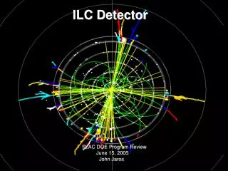
ILC Detector. ILC Detector. SLAC DOE Program Review June 15, 2005 John Jaros .

ILC Detector
E N D
Presentation Transcript
ILCDetector ILC Detector SLAC DOE Program Review June 15, 2005 John Jaros SLAC DOE Program Review June 15, 2005 John Jaros
Goal: Design and Develop a Detector for the ILC There are three interrelated activities at SLAC supporting ILC detector design and development: • Machine-Detector Interface Studies/Designs/Experiments • Physics and Detector Simulation/Computing Infrastructure • Silicon DetectorDesign June 15, 2005 John Jaros
ILC Physics demands advances in detector design and technology, starting with Calorimetery… Bread and Butter Precision EW or Measure Higgs Self Coupling hhhSignal of Strong EWSB? Unconstrained kinematics needs Tiny (0.2 fb @ 500 GeV) signalhigh resolution cal to discriminate on large multi-jet backgrounds WW, WZe, and ZZ events. is only visible with high resolution June 15, 2005 John Jaros
Higgs Studies require superb Tracker Momentum Resolution… • Higgs recoil mass resolution improves until p/p2 ~ 2 x 10⁻⁵ . Accuracy of higgs mass determination, sensitivity to invisible higgs decays, and purity of recoil-tagged higgs sample, improve accordingly. (Yang and Riles. Nominal p/p2~ 3 x 10⁻⁵ ; 1% beam E spread) • Tracker resolution improvement is 10X LEP/SLC and 3X CMS.New territory. June 15, 2005 John Jaros
…and push Vertex Detector Impact Parameter Resolution • Precision measurements of Higgs branching fractions test how the Higgs generates the fermion and gauge boson masses, and can discriminate SM and MSSM behavior. Need ~few m resolution, thin layers, small radius beam pipe. • Real Challenge: Reading out a pixel VXD fast enough to avoid being swamped by pairs background from 3000 bunch crossings. No proof of principle exists. June 15, 2005 John Jaros
Spectrometer Magnet BPMs Ancillary Magnet 2.5cm a = 1.9 mrad 10m 0m Precise Differential Luminosity (dL/dE) and Ebeam Measurements Push the State of the Art Top threshold scan and slepton masses need precise luminosity spectrum information. Measure Bhabha Acolinearity (/ ~ 10-5 very demanding)S. Boogert, SLAC MDI 1/05) Higgs and top mass precision set E/E requirement (200ppm). Beam Deflection with Precision Bend and BPMs measures E.(M. Hildreth, SLAC MDI, 1/05) June 15, 2005 John Jaros
Detector Design/Development needed NOW to move ILC along • Barry’s ILC timeline pushes the Detector Schedule. Detector R&D Needs due late 2005; Detector Concepts and Costs due 2006; Detector CDR needed prior to Machine TDR. • Significant R&D challenges need time: 1k channel, low power ASICs; fast vxd readout technologies; digital hadron calorimetry; beamline instrumentation. • US ILC R&D commitment dangerously behind European effort. Can’t afford to miss this opportunity. June 15, 2005 John Jaros
ILC Machine-Detector Interface @ SLAC • Expert Group at SLAC straddles machine/detector boundary • LCD ILC • Takashi Maruyama Ray Arnold • Ken Moffeit Lew Keller • Mike WoodsTom Markiewicz • Andrei Seryi + many others • Principal Accomplishments • Reevaluate pair backgrounds for ILC parameters (see below) • Full IR Design for 2 and 20 mr crossing angles • Design beam energy spectrometer (with U Oregon and Notre Dame) • Study luminosity spectrum and beam energy measurements (with U Oregon) • Investigate EMI (electro-magnetic interference) and beam rf effects • Help design and evaluate polarimetry and posipol Pair Production and Capture at IR Pair Energy (GeV/pixel)—Beam’s Eye View June 15, 2005 John Jaros
SLAC MDI Activities are Internationally Connected • 1.ALCPG Working Group on Interaction Regions, Backgrounds. • WG convenors are S. Hertzbach (UMass), T. Markiewicz (SLAC). • http://www-project.slac.stanford.edu/lc/bdir/index.htm • ALCPG Working Group on IP Beam Instrumentation. • WG convenors are E. Torrence (U. of Oregon) and M. Woods (SLAC). • http://www.slac.stanford.edu/xorg/lcd/ipbi/ • 3.MDI Workshop held at SLAC, Jan 2005. ~100 participants from all 3 regions. • http://www-conf.slac.stanford.edu/mdi/ • 4. MDI Panel formed by the WWS at LCWS05. Interim members are • P. Bambade (LAL-Orsay), T. Tauchi (KEK), M. Woods (SLAC) • 5. R&D program in End Station A for prototypes of beam delivery and IR components. • http://www-project.slac.stanford.edu/ilc/testfac/ESA/esa.html • SLAC Experiments T-474,475 Energy Spectrometer prototypes • New Proposal? EMI from short pulses • Another ILC Detector Test Beam? June 15, 2005 John Jaros
Simulation/Computing Infrastructure Strong group at SLAC has supported American (ALCPG) and International LC Physics and Detector Studies Simulation/Infrastructure Algorithm Development/SupportR. Cassel S. Magill (Argonne visitor)N. Graf(seetalk in breakout) B. Schumm (UCSC)T. Johnson N. Sinev (U Oregon)J. McCormick S. Wagner (U Colorado) E. von Toerne, D. Onoprienko (U Kansas) W. Mader, M. Charles, N. Torson (U Iowa) + more coming Principal Activities • ProducedFull Featured Geant 4 Simulation Package XML input description, standard LCIO output. • Event generation, event libraries, full SM physics suite • Algorithm development, Pattern Recognition Code, Detector Digitization Models • Documentation and tutorials • Preparations for Snowmass: Software Intro, Code, and Tools June 15, 2005 John Jaros
Geant4 Sim Package Input Example: XML definition for SiD VXD • 5 Layer CCD Barrel • 4 Layer CCD Disks • Be supports • Foam Cryostat <detectors> <detector id="0" name="BarrelVertex" type="MultiLayerTracker" readout="VtxBarrHits"> <layer id="1" inner_r = "1.5*cm" outer_z = "6.25*cm"> <slice material = "Silicon" width = "0.01*cm" sensitive = "yes" /> </layer> <layer id="2" inner_r = "2.6*cm" outer_z = "6.25*cm"> <slice material = "Silicon" width = "0.01*cm" sensitive = "yes" /> </layer> <layer id="3" inner_r = "3.7*cm" outer_z = "6.25*cm"> <slice material = "Silicon" width = "0.01*cm" sensitive = "yes" /> </layer> <layer id="4" inner_r = "4.8*cm" outer_z = "6.25*cm" > <slice material = "Silicon" width = "0.01*cm" sensitive = "yes" /> </layer> <layer id="5" inner_r = "6.0*cm" outer_z = "6.25*cm"> <slice material = "Silicon" width = "0.01*cm" sensitive = "yes" /> </layer> </detector>
The Silicon Detector Concept SiD starting assumptions…Calorimetry drives the detector design Particle Flow calorimetry delivers the best performanceSi/W is the right technology for the ECAL, but expensive Optimize performance, constrain costs therefore…SiD Starting Point$ Limit calorimeter radius and lengthBoost the B field to recover BR2 for particle flow, improve momentum resolution for tracker, reduce backgrounds for VXD Use Si microstrips for compact, robust, high precision trackingExploit VXD and ECAL pattern recognition capability for tracking June 15, 2005 John Jaros
SiD Detector Design Study is International Design Study Coordinators J. Jaros and H. Weerts Asian and European Contact Persons H. Aihara and Y. Karyotakis SiD Executive Committee Design Study Coordinators SiD R&D Coordinator A. White Godfathers M. Breidenbach and J. Brau SiD Advisory Group SiD Executive Committee Working Group LeadersSiD Working GroupsBenchmarking (T. Barklow), Calorimetry (R. Frey, J. Repond), Costs (M. Breidenbach), Magnet/Flux Return (R. Smith, Saclay, KEK), Muons (soon!), Simulation (N. Graf), Tracking (M. Demarteau, R. Partridge), Vertexing (D. Su), MDI (P. Burrows, T. Tauchi) some international flavor, needs some more June 15, 2005 John Jaros
Silicon Detector Design and Development@ SLAC SLAC ParticipantsT. Barklow R.Cassel (+Sim) M. Breidenbach N. Graf (+Sim) J. Jaros T. Johnson (+Sim) T. Maruyama (+MDI) T. Markiewicz (+ILC) S. Magill (Argonne visitor) K. Moffeit (+MDI) T. Nelson M. Woods (+MDI) N. Sinev (U Oregon visitor) Major Activities are closely integrated with FNAL, BNL, Argonne, UO, UCSC, Brown, Iowa, Kansas,… • Pattern Recognition Code for Tracker and Calorimeter • Front-end electronics design for Si/W ECAL, microstrips • Physics Analysis and Detector Benchmarking • Tracker and microstrip detector module design • VXD Concept • Costing Tools Next Year Needs More M&S, Engineering, and Simulation Support • Expand simulation support and code development • Submit and test Si/W front end chip, Prototype ECAL Module • Prototype Tracker Detector Module and Readout Chip June 15, 2005 John Jaros
Particle Flow Algorithms Promise High Resolution The Idea of Particle Flow Calorimetry • Measure charged energy in tracker • Excluding charged energy depositions in ecal, measure photonshower energy • Excluding charged and emneutrals, catch remaining hadronicenergy in ecal and hcal Measure energies of individual particles,not energy deposition in cal modules. Algorithm development underway (N. Graf, S. Magill, et al.)Find/Remove Clusters from Tracks Calibrate and Tune Cal Response • Photons in ECAL • -> sf = 0.012 • KL0 in HCAL • -> sf = 0.06 June 15, 2005 John Jaros
Pixelating the EM Calorimeter P-Flow requires high transverse and longitudinal segmentation,dense medium. SiW can provide 5 x 5 mm2 segmentation and minimal effective Moliere radius to limit transverse shower size. Cost and power consumption are the issues. Silicon Wafer June 15, 2005 John Jaros
SLAC/Oregon/BNL Readout Chip for SiW ECAL 1024 channel bump-bonded ASIC, pulse height and timeper pixel (X10 current ASICs) Power cycling – only passive cooling required (<40mW/chip)Dynamic range OK for ECAL(0.1 - 2500 mip) Pulse Height and Bunch Time buffered 4 deep to accommodate multiple hits in long ILC pulse trainReady for prototype submissionin one month. June 15, 2005 John Jaros
Si-W Pixel Analog Section • SLAC • D. Freytag • G. Haller • J. Deng • M.Breidenbach • Oregon • J. Brau • R. Frey • D. Strom • BNL • V. RadekaChip will be adapted to readout 1-2k channel Si microstripdetectors, also power pulsed, time stamped, and buffered. June 15, 2005 John Jaros
Si-W Single Channel Layout June 15, 2005 John Jaros
Bonus of a Tracking Calorimeter Track from outside in: K0s and or long-lived SUSY! June 15, 2005 John Jaros
Physics Needed Performance T. Barklow and SiD Benchmarking Group are revisiting detector performance goals, closely watching the physics payoff. High performance tracking can exploit excellent ILC beam energy spread. Will study errors vs costs. June 15, 2005 John Jaros
SiD Tracker is a Collaborative Effort SiD Starting Point: High Precision, Robust to Backgrounds, Thin • p/p2 ~ 2 x 10⁻⁵ FNAL Layout&Support • Time resolves single bunches, eliminatingbackgrounds • Pattern recognition robust to pair backgrounds(200X nominal background still OK) • Thin: 1.3% x/x0 per layer. Won’t obscure ECAL or forward tracking. • Si stands up to errant ionization losses. Design has evolved in collaboration with FNAL, Brown, and UCSC:FNAL/SLAC mechanics SLAC performance studies, module design, readout and electronics June 15, 2005 John Jaros
SiD VXD Concept Exploit pattern recognition capability of 5 pixel layers to initiate tracking. Endcaps provide forward solid angle coverage, improve forward impact parameter resolution, and provide superb forward angular resolution. Work is focusing on design and materials issues for the VXD endcaps, and new pixel technologies that can handle the 1/mm2 /bunch-crossing backgrounds. CMOS looks very interesting. June 15, 2005 John Jaros
Detector Optimization needs Detector Costs M. Breidenbach has developed an EXCEL spreadsheet for costing the SiD Detector. • Parameterizes the major subdetector boundaries, layers, thicknesses, etc. • Puts in costs for materials (per kg for absorber) • Costs for detector elements ( per m2) • Costs for electronics • Includes solenoid cost model • Creates sliders to change parameters like absorbers, gaps, barrel/forward transition, BR2, HCAL in or out of coil, etc. and study cost variations. Discussions with other concept studies are planned in the near future. W ; sample 0.7cm =2X0 55 samples; 4 L 110 X0 ; DR=0.94m June 15, 2005 John Jaros
Conclusions Physics demands advances in ILC detector designs and new detector technologies. NOW. Strong local efforts in MDI and Simulation/Computing support ILC Detector Development at SLAC. The SiD Design Studyhas engaged a national and international community to optimize the SiD design. Lots planned for Snowmass. Strong start on SiD R&D: Si/W and strip electronics, Tracker Design, Physics studies, Pat Rec and Particle Flow Algorithms Immediate Plans: ECAL prototype, strip readout, detector readout modules, SiDoptimization. We need more M&S and engineering support to accomplish our plans. June 15, 2005 John Jaros
Forward Tracking Becomes Critically Important • Good jet-mass reconstruction needs calorimetry and tracking overthe full solid angle: |cos| 0.98. • Forward tracking must be thin enough not to degrade forward calorimetry or spoil electron ID and robust enough to track loopers and K shorts. • Differential luminosity measurement requires extremely precise angularmeasurements: /~10-5 • Never been done (right)! June 15, 2005 John Jaros
High Field, High Stored Energy Solenoids need Development • Current LC detector concepts use 3-5T solenoids with GJ stored energies. The CMS coil is the lone prototype for such magnets. Serious engineering design and cost optimization is required. Design requires dipole compensation for finite crossing angle. Stored E [GJ] Field Uniformity Required? Cost Br [M$] CMS Coil June 15, 2005 John Jaros