Installation and Commissioning Workshop for Forward Multiplicity Detector (FMD)
130 likes | 265 Views
This workshop focused on the installation and commissioning of the Forward Multiplicity Detector (FMD) at the Niels Bohr Institute. Key elements discussed included mechanical assembly, electronics, cabling, and integration testing at CERN. The timelines for equipment arrivals and installation dates for FMD1, FMD2, and FMD3 were reviewed, along with pre-commissioning plans and testing requirements. The session addressed operational prerequisites and roles for the installation team before the detector integration into the experimental setup.

Installation and Commissioning Workshop for Forward Multiplicity Detector (FMD)
E N D
Presentation Transcript
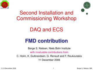
1st Installation and Commissioning Workshop Forward Multiplicity Detector (FMD) Borge S. Nielsen, Niels Bohr Institute
Forward Multiplicity Detector (FMD) ITS Outer ring Inner ring FMD 3 FMD 1 FMD 2 Borge S. Nielsen, Niels Bohr Institute
Detector elements Muon absorber cabling Final “Inner” Digitizer Final FMD3 cone with beam pipe support Complete module (“outer” type) Cone assembly test Borge S. Nielsen, Niels Bohr Institute
System tests already done Mechanical assembly with models at CERN Beam tests with >5000 active channels and 2 digitizer cards +1 RCU+DATE Full read-out tests with Digitizer+RCU+DATE Borge S. Nielsen, Niels Bohr Institute
Pre-commissioning • Pre-commissioning plans prior to installation @NBI: - assemble complete detectors (FMD3 + FMD2, then FMD1) - complete test with RCU, DDL, DATE, TTC/LTU, cooling (but not final CAEN LV and HV) - basic DCS panels, tested on simulated CAEN and real RCU/DCS card @CERN (Jan-Feb 2007): - retest as above, but with ‘final’ CAEN power supplies • Status of pre-commissioning (@NBI) - FMD3 mechanics ~ready, FMD2 starting production - all detector modules in house - TTC/LTU being set up - cooling plates in production - DCS work starting - complete read-out working Borge S. Nielsen, Niels Bohr Institute
Electronics & Racks • Locations of racks in the cavern + drawings of rack content including rack patch-panels and possible communication lines between racks and entry point of cables (top, bottom ?) - Rack O13 contains one EASY 3000 crate with 48 V power supply etc one patch panel to distribute the LV cables from 10 digitizers and 3 RCUs to 4 low voltage modules - Rack X06 contains one SY1527 crate one patch panel to distribute the HV cables from 70 modules and 6 high voltage modules • Schedule for arrival of electronics and individual rack components at CERN. - Power supply crates hopefully early 2007 - Power supply modules before August 2007 – delivery schedule unknown - Patch panels to be mounted together with cable connectors • Electronics commissioning - Power supplies to be installed and commissioned together with FMD3 Borge S. Nielsen, Niels Bohr Institute
Detector Arrival @ CERN Installation dates: FMD3 16-20 February 2007 FMD2 07 March 2007 FMD1 03-05 July 2007 • When will the detector arrive at CERN ? - before mid January 2007 (FMD3 and FMD2, FMD1 later) • What are the dimensions of the ‘transport cradle’ that must be brought to the place of installation ? How will it be brought there? - 2 times 1x1x1 m3 by car • How many people will participate in the installation ? - 6-8 people (physicists and technicians) • How many days before installation will the team arrive ? - early-mid January for lab. test: 3-4 people - for installation: above + 3-4 people Borge S. Nielsen, Niels Bohr Institute
Cables & Patch panels • Status of cable, fibre and connector ordering. - C side cables on absorber done, remaining defined but cables not pulled. Fibres not pulled. - A side ~defined, but missing final cable lengths and final patch panel designs. • Plans for cabling, connector and cable testing activity by subgroup. - NBI: - cables on absorber and service chariot - all cable connectors - full cable testing - CERN: - pull long cables and all fibres • Needed patch panels and status of patch panels. - Still to be done: panels on A side (PP2, PP1, PP0) panels in racks (LV and HV distributions) Borge S. Nielsen, Niels Bohr Institute
Installation (1) • Minimum status of services at start of installation. - all cables and fibres ready and tested - LTU/TTC running - DAQ running - CAEN HV and EASY LV crates and ‘some’ modules delivered - preferably cooling water from TPC heat screen system • Installation tooling provided by the subdetector group. - support for cones during assembly • Other Infrastructure needed. - full ITS installation infrastructure • Installation scenario – day by day. - Before installation date: install and cable RCU modules - FMD3: 3 days mechanical installation, then complete test - FMD2: 1 day mechanical installation 1 day (12/03/2007) set aside for complete test after the cable hook-up Borge S. Nielsen, Niels Bohr Institute
Installation (2) • Tests and verifications during installation for cables, fibers and cooling lines. - cables etc should be tested before installation - FMD3 should be verified through to the racks and counting rooms (with DCS and DAQ) - FMD2 cannot be cabled until TPC is in place – ideally detector should be tested with the commissioning electronics; Not clear what is possible with temporary cabling, power etc. • Alignment requirements - assured at required precision by ITS installation scenario Borge S. Nielsen, Niels Bohr Institute
Commissioning – summary (1) At NBI: • Test all detector modules at NBI. • Results stored in systematic fashion. Make list of repairs, send modules to CERN. • Pre-assembly at NBI • Cables • Shielding (HF and light) • Cooling • Mechanical fit. Detectors, Honeycomb, Digitizer, beam tube support. • Noise tests • RO system w. 2 branches • Calibration pulse test • DCS control software • Monitor software, test and calibration scripts. • Check safety procedures (leakage current, auto shut off at beam injections, etc…) • Final e-beam test at Aarhus – data taken 4-5 November • Test inner and outer digitizers with. inner and outer detectors. • S/N systematics • Rate dependence • System stability • Limitations at NBI • Real LV and HV not available • Final assembly at NBI - December Borge S. Nielsen, Niels Bohr Institute
Commissioning – summary (2) At CERN: • Detector operation at CERN in Lab. – conditions similar to NBI lab. • (Re-) Assemble detector system after transport • Connect detectors to LV, HV, and self-generated trigger • Run with stand-alone DAQ • Operate system in lab. Measure noise, stability and rate • Detector operation at CERN in Lab. – conditions similar to ALICE. • Connect detectors to ‘real’ LV, HV, and trigger • Establish DCS control of hardware • Run with ‘real’ external trigger (LTU/TTC) and real ALICE DAQ • Operate system in lab. Measure noise, stability and rate • Calibration and Control procedures • Exercise scripts to calibrate (pedestals, gain) and operate detector (start/stop/reset/load) • Exercise first monitor programs • Check stability and rate performance • Check safety procedures (leakage current, auto shut off at beam injections, etc…) • Preparation in ALICE (in pit) prior to installation • Verify all cables/connectors (long cables and local (PP-to detector) cables) • Availability of trigger signal • Availability of real HV, LV - LV situation problematic due to CAEN delivery schedule • Availability of DCS control • Availability of DAQ • Installation (3 days for FMD3, 1 day for FMD 2, 3 Days for FMD 1) • Run all scripts repeatedly and measure noise performance for entire system in situ (Requires HV,LV, Trigger and DAQ, partly DCS) Borge S. Nielsen, Niels Bohr Institute
Commissioning – summary (3) At CERN post installation: • Detector operation in ALICE. • Connect detectors to ‘real’ LV, HV, and trigger • Establish DCS control of final hardware • Run with real external trigger (TTC) and real ALICE DAQ • Operate system in ALICE. Measure noise and stability. • Calibration and Control procedures • Exercise scripts to calibrate (pedestals, gain) and operate detector (start/stop/reset/load) • Exercise first monitor programs • Check stability and rate performance Borge S. Nielsen, Niels Bohr Institute