Download
1 / 24
240 likes | 260 Views
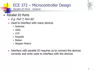
ECE 372 – Microcontroller Design Parallel IO Ports - Outputs. Parallel IO Ports E.g. Port T, Port AD Used to interface with many devices Switches LEDs LCD Keypads Relays Stepper Motors

E N D
ECE 372 – Microcontroller DesignParallel IO Ports - Outputs • Parallel IO Ports • E.g. Port T, Port AD • Used to interface with many devices • Switches • LEDs • LCD • Keypads • Relays • Stepper Motors • Interface with parallel IO requires us to connect the devices correctly and write code to interface with the devices
ECE 372 – Microcontroller DesignParallel IO Ports - Outputs • HCS12 – Where can we connect external hardware? • Unused ports (every port has DIO functionality) • Expand through the serial interface • SPI serial peripheral interface • SCI serial communication interface RS232
ECE 372 – Microcontroller DesignParallel IO Ports - Outputs • HCS12 – Where can we connect external hardware? • Port B and A are not connected except PB4 and PA0 • Port S0,1 is RxD and TxD for SCI • Port M2,3,4,5 are used for SPI • Port M0,1 are used for CAN • Port P is cross connected with Port T except PP5 • Port T0..7 can be sued for timer I/O and PWM • Port A/D 0...7 is used for A/D input
ECE 372 – Microcontroller DesignParallel IO Ports - Outputs • Directly Controlling LEDs • HCS12 can directly control LED from output ports • Why would we NOT want to do this? 5V 5V 5V 5V Micro-controller
ECE 372 – Microcontroller DesignParallel IO Ports - Outputs • Simple LED • Output Port is High - LED is On • 7405 inverter output will be low • Current flows through 7405 to ground • Output Port is Low – LED is Off • 7405 inverter output will be high impedance • No current flows through 7405 • Resistor used to control brightness: LED is about 2V, 10-20mA
ECE 372 – Microcontroller DesignParallel IO Ports - Outputs • LED – Open Collector • NPN transistor is On if Vb is High • LED will be On is Vb is High • Can support up to 250mA Micro-controller C NPN
ECE 372 – Microcontroller DesignParallel IO Ports - Outputs • LED – Open Emitter • PNP transistor is On if Vb is Low • LED will be On is Vb is Low • Can support up to 250mA E Micro-controller PNP
ECE 372 – Microcontroller DesignParallel IO Ports - Outputs • Directly Controlling LEDs • We can use external IC to drive the LEDs • Reduce current driven by microcontroller and protects it • 74LS244IC Tri-state Buffer/Line Driver/Line Receiver • Used to provide power for LEDs • Has OE signals that can be used to disable the output OE1 OE2 A8 A8 Micro-controller A7 A7 A6 A6 A5 A5 A4 A4 A3 A3 A2 A2 A1 A1 74LS244
ECE 372 – Microcontroller DesignParallel IO Ports - Outputs • Directly Controlling LEDs • Limitation - Can only drive as many LEDs as available pins • Solutions: • Latching • Scanning • Multiplexing OE1 OE2 A8 A8 Micro-controller A7 A7 A6 A6 A5 A5 A4 A4 A3 A3 A2 A2 A1 A1 74LS244
Latch Latch OE OE LE LE A8 A8 A8 A8 A7 A7 A7 A7 A6 A6 A6 A6 A5 A5 A5 A5 A4 A4 A4 A4 A3 A3 A3 A3 A2 A2 A2 A2 A1 A1 A1 A1 ECE 372 – Microcontroller DesignParallel IO Ports - Outputs • LEDs - Latching • Control LED by using a latch hardware • Use additional hardware to control when to latch values • Similar to memory mapped IO LED Address Micro-controller LED Data Address=0 Address=1
Latch Latch OE OE LE LE A8 A8 A8 A8 A7 A7 A7 A7 A6 A6 A6 A6 A5 A5 A5 A5 A4 A4 A4 A4 A3 A3 A3 A3 A2 A2 A2 A2 A1 A1 A1 A1 ECE 372 – Microcontroller DesignParallel IO Ports - Outputs • LEDs - Latching • Control LED by using a latch hardware • Use additional hardware to control when to latch values • Similar to memory mapped IO Always writing last LED value! Any problems?? Addr Micro-controller Address=0 Address=1
Latch Latch OE OE LE LE A8 A8 A8 A8 A7 A7 A7 A7 A6 A6 A6 A6 A5 A5 A5 A5 A4 A4 A4 A4 A3 A3 A3 A3 A2 A2 A2 A2 A1 A1 A1 A1 ECE 372 – Microcontroller DesignParallel IO Ports - Outputs • LEDs - Latching • Add enable signal from microcontroller What did we build? Is there another way to implement the address decoding? Micro-controller En Addr Address=0 Address=1
d0 d1 d2 d3 d0 d1 i0 i1 d2 d3 e i1 i0 ECE 372 – Microcontroller DesignParallel IO Ports - Outputs • LEDs - Latching • Use decoder for addressing LED banks • Decoder - Converts input binary number to single high output • 2-input decoder: four possible input binary numbers • Thus, four outputs, one for each possible input binary number • Enable signal • Outputs all 0 if e=0 • Regular behavior if e=1 i1’i0’ i1’i0 i1i0’ i1i0
en d0 d1 i0 1x2 Decoder Latch Latch OE OE LE LE A8 A8 A8 A8 A7 A7 A7 A7 A6 A6 A6 A6 A5 A5 A5 A5 A4 A4 A4 A4 A3 A3 A3 A3 A2 A2 A2 A2 A1 A1 A1 A1 ECE 372 – Microcontroller DesignParallel IO Ports - Outputs • LEDs - Latching • Use decoder for addressing LED banks Micro-controller En Addr Address=0 Address=1
ECE 372 – Microcontroller DesignParallel IO Ports - Outputs • LEDs - Scanning • Use software executing on the microcontroller to control LEDs row by row, col by col, or bank by bank (depending on organization) • Operation • Continually scan LEDs fast enough that human eye cannot detect it • Similar to refresh rate of TVs and Monitors • Enable one column of LEDs by writing 0 to output port controlling desired column • Write LEDs value for select row • Cannot access all LEDs simultaneously Micro-controller Row Data Column Select
ECE 372 – Microcontroller DesignParallel IO Ports - Outputs • LEDs - Multiplexed • Use software executing on the microcontroller to control LEDs one at a time • Operation • Continually scan LEDs fast enough that human eye cannot detect it • Similar to refresh rate of TVs and Monitors • Enable LED column by outputting column address to column decoder • Enable individual LEDs by outputting row address to row decoder • Cannot access all LEDs simultaneously Micro-controller 4x16 dec 4x16 dec
ECE 372 – Microcontroller DesignParallel IO Ports - Outputs • How many LEDs can I control using only eight output pins using the following schemes? • Latched: • Scanned • Multiplexed:
ECE 372 – Microcontroller DesignParallel IO Ports - Outputs • How many LEDs can I control using only eight output pins using the following schemes? • Latched: • 64 LEDs – Individual latch used for each LED • 1 Enable Output, 6 Address Lines, and 1 Data Line • Six address lines allow for access to 26 latches (or LEDs) • Scanned • 16 LEDs – 4 columns by 4 rows • Multiplexed: • 256 LEDs – 16 columns by 16 rows • Enabled by using 4x16 decoder to select both row and columns
ECE 372 – Microcontroller DesignParallel IO Ports - Outputs • Mill Game • How many pins do we need to connect the 48 LEDs in the following diagram?
ECE 372 – Microcontroller DesignParallel IO Ports - Outputs • Mill Game
ECE 372 – Microcontroller DesignParallel IO Ports - Outputs • 7-Segment LEDs Micro-controller Common Cathode
ECE 372 – Microcontroller DesignParallel IO Ports - Outputs • 7-Segment LED – Design Example • Control three 7-segment LED displays • Scanning through the entire display must happen faster than the human eye can detect (> 40 Hz) • The LED must look like it is continuously on at 10 mA • Average current = 10 mA
ECE 372 – Microcontroller DesignParallel IO Ports - Outputs • 7-Segment LED – Design Example • Use scanning to control 7-segment LEDs 7447 – BCD to 7-Segment Display Micro-controller
ECE 372 – Microcontroller DesignParallel IO Ports - Outputs • 7-Segment LED – Design Example • Use scanning to control 7-segment LEDs Current (mA) 10 mA DC 30 Time (ms) 15 30 1/15 ms > 66 Hz