Download
1 / 14
140 likes | 328 Views
A System View of Optical Fiber Communication prt.2. AbdulRahman AlKhayyat 223218 Mohamed Felimban 224304. OUTLINE. The Fiber Optic Data Communication System Components of the Transmission System Transmitters Receivers Transmission Medium Performance Attenuation Interference

E N D
A System View of Optical Fiber Communication prt.2 AbdulRahman AlKhayyat 223218 Mohamed Felimban 224304
OUTLINE • The Fiber Optic Data Communication System • Components of the Transmission System • Transmitters • Receivers • Transmission Medium • Performance • Attenuation • Interference • Conclusion
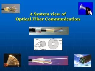
I. The Fiber Optic Data Communication System Fiber Optic communication systems generally include: • A Transmitter • Transmission Medium including amplifiers and repeaters • A Receiver A model of this System is shown in the figure The illustration indicates the Source-User pair, Transmitter & Receiver It also clearly shows the Transmission Medium.
II. Components of the Transmission System • Transmitter to convert an electrical signal into an optical signal serves two functions: • A light emitter works as a source of the light coupled into the fiber optic cable • A regulator to modulate this light to represent the binary data it receive
II.1. Transmitters: Optical Source Component There are some requirements for the transmitter that should be met • physical dimensions must be compatible with size of the fiber optic being used • emit light in a cone within cross sectional diameter • optical source must be able to generate enough power • desired BER should be met • high efficiency in coupling the light into the fiber optic cable • sufficient linearity • to prevent the generation of harmonics & inter-modulation distortion • if such interference is generated it is extremely difficult to remove • this would cancel the interference resistance benefits of the fiber optic cable • Should be easily modulated with an electrical signal & capable of high-speed modulation • The usual requirements of small size, low weight, low cost and high reliability
II.1. Transmitters cont’d • Types of Diodes that can be used as an optical source of the Transmitter: • laser diode (LD) • light emitting diode (LED) • LD's advantages over LED's • can be modulated at very high speeds • produce greater optical power • higher coupling efficiency to the fiber optic cable
II.1. Transmitters cont’d • LED's advantages over LD's • higher reliability • better linearity • lower cost LED and laser diodes: P-I characteristics VerschiedeneLED’s
II. Components of the Transmission System • Receivers to recover the signal as an electrical signal serves two functions: • A sensor to detect the light coupled out of the fiber optic cable then convert the light into an electrical signal • A demodulator demodulate this light determine the identity of the binary data that it represents Indoor & Outdoor Receivers
II.2. Receivers cont’d Receiver sensitivities for BER = 10-9, with different devices • receiver performance is generally characterized by a parameter called the Sensitivity • usually a curve indicating the minimum optical power that the Receiver can detect versus the data rate, in order to achieve a particular BER
II.3. Transmission Medium • The Transmission distance is limited by • fiber attenuation & fiber distortion • Solution: i. repeaters • convert the signal to an electrical signal • send the signal again at a higher intensity • high complexity & needing to be installed once every 20km = very high cost • Solution: ii. optical amplifiers • amplifies the optical signal directly without converting the signal into the electrical domain • Amplifiers have largely replaced repeaters in new installations
III. Performance • The more light that can be coupled into the core the more light will reach the Receiver and the lower BER • The lower attenuation in propagating down the core the more light reaches the Receiver & the lower BER • The less time realized in propagating the faster the signaling rate and the higher the end-to-end data rate from Source-to-User
III. Performance cont’d • Attenuation • Caused by a combination of material absorption, Raleigh scattering, Mie scattering, and connection losses • Is about 1000 db/km in modern fiber • Other causes of attenuation are physical stresses to the fiber, microscopic fluctuations in density, and imperfect splicing techniques. Attenuation vs. WavelengthAttenuation spectrum of standard single-mode fiber
III. Performance cont’d • Interference • a key concern is the problem of interference • Presence of high current equipment results in the propagation of electromagnetic pulses that interfere with the data communications links • In the past UTP copper cable was the transmission medium choice • Using Fiber optic cables as the Transmission Medium • great interference protection • is simply not affected by the electromagnetic interference • Has been slow in coming to the industrial environment due to cost • however, this is changing as the price of fiber optic cable steadily decreases
IV. In Conclusion Thank You for listening If any question.. We’d be happy to answer