Download
1 / 34
340 likes | 685 Views
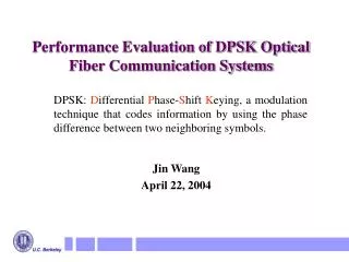
Performance Evaluation of DPSK Optical Fiber Communication Systems. DPSK: D ifferential P hase- S hift K eying, a modulation technique that codes information by using the phase difference between two neighboring symbols. Jin Wang April 22, 2004. Outline. Introduction

E N D
Performance Evaluation of DPSK Optical Fiber Communication Systems DPSK: Differential Phase-Shift Keying, a modulation technique that codes information by using the phase difference between two neighboring symbols. Jin Wang April 22, 2004
Outline • Introduction • Bit Error Analysis in DPSK Systems • Transmission Impairments in DPSK Systems • Electrical Equalizer in DPSK Systems • Nonlinear DPSK Systems
Information Bits Photodetector Laser Optical signal OpticalFilter Decoder Symbols Optical signal Bits Elec.Filter Encoder Modulator Communication Channel Optical Receiver Optical Transmitter One Span ~ 80 km for terrestrial system Optical Fiber Optical Amplifier Typical Long-Hual Optical Communication System Performance measure: Bit Error Ratio (BER). Required: 10-9 ~ 10-14. Dominant noise is Amplified-Spontaneous-Emission (ASE) noise from optical amplifiers. Capacity record (2002): 40 Gb/s/channel, 64 channel, 4000 km, BER < 10-12. Using DPSK.
Modulation Formats Electric field of optical carrier: E(t) = êAexp(jwt+f) One or more field properties can be modulated to carry information. Example: • On-off keying (OOK): binary amplitude modulation • Binary DPSK, Quadrature DPSK : phase modulation • Quadrature Amplitude Modulation (QAM): amplitude and phase modulation Amplitude Polarization Frequency Phase
DPSK in Optical Systems • Early Experiments ( ~ 1990) • For the improvement of receiver sensitivity (At BER 10-9, 1000 photons/bit for OOK v.s. < 100 photons/bit for DPSK) • Low bit rate: ~ 1 Gb/s • Cooling ( 90’s ) After the Advent of Optical Amplifiers • High sensitivity OOK receiver (<100 photons/bit) can be realized with the aid of optical amplifier (Ex. Erbium-Doped Fiber Amplifier) • Complicated DPSK transmitter and receiver • Stringent requirements on laser linewidth (< 1% of data rate) • Recent Revival ( ~ 2002) • For the improvement of receiver sensitivity (< 50 photons/bit), reduction of fiber nonlinearity and increase of spectrum efficiency • Interferometric demodulation + direct detection • Data rates of 10 Gb/s and 40 Gb/s relaxed linewidth requirements
Opticalfilter LaserMod. i 0 1 On-Off Keying (OOK) OOK System: Bits E(t) G i Electricalfilter 1 0 1 1 E(t) Bit set {0, 1} symbol set {0, 1}. One symbol transfers one bit information. Easy to modulate and detect. Non-return-to-zero (NRZ) OOK Signal E(t) t Return-to-zero OOK Signal t Detected Signal: Symbol constellation for OOK Signal-ASE beat noise is dominant noise Im{E} Probability density function of i Re{E} 0 1
+ 1 0 Im{E} 1 0 -1 1 i Re{E} 0 1 Binary DPSK (2-DPSK) 2-DPSK System: i Ts Elec.Filter E(t) Bits Differential Encoder Optical Filter Laser Mod. G Es Interferometer 1 0 0 1 E(t) Bit set {0, 1} symbol set {-1, 1} i.e. {ej , ej0} One symbol transfers one bit information Bit 0: leave phase alone, bit 1: introduce a p- phase change NRZ-2-DPSK signal t E(t) RZ-2-DPSK signal t Symbol constellation
4-DPSK System: Ts Elec.LPF iI E(t) Bits Optical BPF Differential Encoder Laser Mod. G Ts iQ Elec.LPF 90o EQ iQ 00 00 11 01 10 11 01 01 10 EI 00 iI 11 10 01 11 10 11 01 00 00 10 Quadrature DPSK (4-DPSK) Bit-pair set {00,01,10,11} symbol set {e± j/4, e± j3/4} One symbol transfers TWO bits of information. Ts= 2Tb. Signal bandwidth is only one half of the bit rate.
Transmission Impairments - I Chromatic Dispersion (CD) • Origin: The refractive index of fiber is frequency dependent. • Analogy: • Linear effect. Baseband TF of fiber: • Phenomenon: pulse broadening intersymbol interference (ISI). CD Parameter, 3 ~ 17 ps/km/nm Fiber length 1 1 1 0 40 km D=17 ps/km/nm 40 km D =17 ps/km/nm 10 Gb/s signal
CD FNL Fiber Loss Transmission Impairments - II Fiber Nonlinearity (FNL) • Origin: The refractive index of fiber is power dependent. • Nonlinear Schrödinger equation (wave equation in fiber): • Effects: • Self-phase modulation (SPM) spectrum broadening. • Cross-phase modulation (XPM) spectrum broadening. • Four-wave mixing (FWM) noise amplification. interchannel crosstalk. • Spectrum broadening + CD intersymbol interference . No analytic solutions for general input, numerical approach necessary (split-step FFT)
fast axis slow axis ideal fiber real fiber Transmission Impairments - III Polarization Mode Dispersion (PMD) • Origin: • Principal states model • Linear effect in optical domain. Baseband TF of fiber with PMD: • PMD stochastic. PMD causes ISI. Impact D. Input field E0(t) D : power splitting ratio. D: differential group delay.
DPSK vs. OOK (ASE dominated) 4 • 2-DPSK vs. OOK: Power FNL , Power variation FNL • 4-DPSK vs. OOK: Spectrum efficiency , CD , PMD , FNL . 16 16 8 8 3 DPSK Relative Bandwidth (Hz) Spectral Efficiency (bits / symbol) PAM (Pulse Amplitude Modulation) OOK is 2-PAM 4 4 2 2 2 1 1 0 3 6 9 -3 12 15 18 Relative Required Light Power (dB) to Achieve 10-9 BER in Ideal System
How Robust is DPSK? CD PMD Impacts on DPSK not quantified before. FNL Reasons for the dearth of impact analysis: • The BER of DPSK systems has been difficult to calculate, because of the squaring effect of photodetector. • The interaction of CD and FNL in fiber increases the difficulty of modeling optical noise in fiber.
OpticalBPF LaserMod. BER Calculation using Eigenfunction Expansion Bits G i ElectricalLPF Neglect fiber nonlinearity e(t) i(t) | .|2 Square in time domain Convolution in frequency domain K(f, f’) Hermitian The 2nd kind of homogeneous Fredholm integral equation: {m(f)} is a complete orthornormal function set Eigenfunction expansion: 2 distribution Noise Signal
BER calculation in DPSK system – II One more step to obtain BER: Moment generating function (MGF) of i(t)is (s), i.e., (s)= E[esi] = Laplace transform of PDF of i(t) di L-1 PDF of i(t) BER (CDF of i(t)) One Integral We use saddle point integration method to calculate the integral of MGF.
Saddle Point Integration • Also called stationary phase method, especially in physics. • Basic idea: For the calculation of line integral : If amplitude f(u) changes slowly compared to phase q(u), the main contribution to the integral comes from very near u0 where the phase is stationary, i.e, q(u) u u0
Accuracy of BER calculation method 10 Gb/s system, with Gaussian optical filter and 5th-order Bessel electrical filter. 4-DPSK 4-DPSK 2-DPSK 2-DPSK OSNR is optical signal-to-noise ratio
Power penalty of CD Power Penalty: To account for the transmission impairments, the increase in the optical power to maintain a fixed BER such as 10-9 . RZ-2-DPSK NRZ-OOK RZ-OOK NRZ-2-DPSK 4-DPSK R: Bit rate, D: CD parameter, L: fiber length R2DL D: CD parameter, R: Bit rate, L: fiber length
Power Penalty of PMD NRZ-OOK and NRZ-2-DPSK RZ-OOK and RZ-2-DPSK NRZ-4-DPSK RZ-4-DPSK D: Differential group delay, Tb: Bit period.
Link Distance Limitation due to PMD RZ-4-DPSK NRZ-4-DPSK Fiber PMD parameter 0.25 ps/
Df Power Penalty of Interferometer Phase Error Ts 0.1 mm path error 15º phase error 4-DPSK 2-DPSK
Electrical Equalizer in Optical Systems Feed-forward equalizer (FFE) … Td Td Td From electrical low-pass filter c1 c2 cM Decided bits d1 d2 dN Data-feedback equalizer (DFE) … Ts Ts Ts Td may be symbol duration or a fraction of it. Electrical equalizer is used to reduce ISI caused by CD, PMD, etc. Electrical equalizer is compact, flexbile, low-cost. High speed electrical equalizers operate at 10 Gb/s and 40 Gb/s. Tap weights can be adapted using Least-Mean-Square (LMS), Q-factor maximization and BER minimization schemes.
Equalizer based on LMS algorithm FFE ek 1 v(t) … T T ek c0 _ c1 cM + + + + 0 yk + + kT Ik dN d1 … T T <ek2> is minimized DFE or
Performance of Electrical Equalizer OOK - CD OOK - PMD DPSK - PMD DPSK - CD
Nonlinear 2-DPSK and OOK Systems E(t) Bits Post-Compensator Receiver Pre-Compensator Transmitter DL= 1176 ps/nm DL= 1176 ps/nm DCF fiber DL= 258 ps/nm Pulses: Chirped RZ (phase varies with power) noise G Light loss in fiber: 0.2 dB/km Nonlinear parameter : 1.5 /W/km 80 km, LEAF fiber DL = 280 ps/nm NF: 4.5 dB • Total link distance 8000 km. • CD of green fiber + CD of blue fiber + CD of Pre, Post-Compensators 0 ( Local high dispersion, global low dispersion ) • Pre-Compensator spreads pulses quickly, realizing quasi-linear transmission.
BER Calculation in Nonlinear DPSK System • No noise model for general nonlinear DPSK or OOK system. • No BER calculation method for general nonlinear DPSK or OOK system. • Q-factor is not a reliable performance measure, especially for DPSK system (2~3 dB OSNR error). • In CRZ-DPSK or CRZ-OOK system, noise can be modeled as additive non-white Gaussian noise because of low fiber nonlinearity. • Non-white Gaussian noise model + eigenfunction expansion method yields accurate BER.
Performance of Nonlinear OOK and DPSK CRZ-OOK CRZ-DPSK Threshold There exists an optimum optical power for both OOK and DPSK systems. DPSK has lower BERs than OOK because of lower FNL.
Fiber Fiber Current Work 4-DPSK long-haul transmission experiment EDFA +21 dBm Coupler VOA 100 km Raman DCF Pol Scr EDFA Fiber +21 dBm Coupler Fiber VOA 100 km DCF Raman 4-10 dB 5.6 dB 3 dB SW 2 Coupler Preamp • Recirculating Loop DMUX / RX SW 1 TX / MUX BERT