Download
1 / 21
310 likes | 522 Views
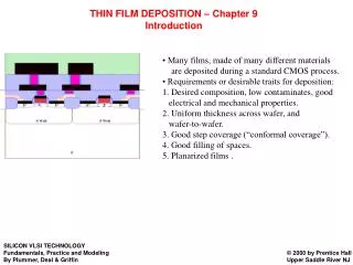
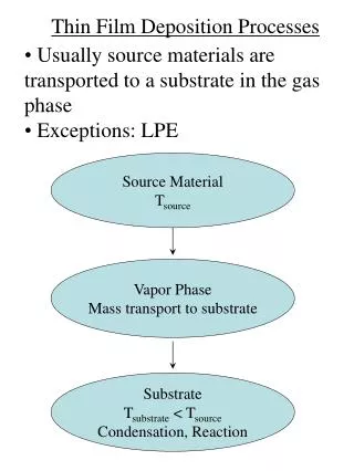
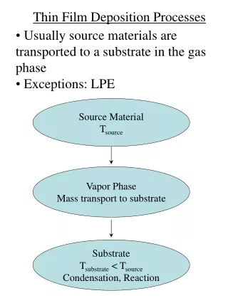
Thin Film Deposition Processes. Usually source materials are transported to a substrate in the gas phase Exceptions: LPE. Source Material T source. Vapor Phase Mass transport to substrate. Substrate T substrate < T source Condensation, Reaction. Thin Film Deposition Technology.

E N D
Thin Film Deposition Processes • Usually source materials are transported to a substrate in the gas phase • Exceptions: LPE Source Material Tsource Vapor Phase Mass transport to substrate Substrate Tsubstrate < Tsource Condensation, Reaction
Thin Film Deposition Technology Thin Film Deposition PVD CVD • Source material enters the vapor phase by physical means (e.g., evaporation, sputtering) • No chemical reactions • Source material is supplied in the form of a precursor gas • Chemical reactions
PVD PVD Resistance-Heated (Thermal Evaporation) Sputtering E-beam Evaporation
Tungsten Filament • Molten beads of metal are retained by surface tension forces on W wires Sheet/Boat Sources • W, Ta, or Mo form boats that contain the evaporant Crucible Sources • Oxide, pyrolytic boron nitride (PBN), or refractory metal containers • Heated by W wire wrapped around the crucible Thermal Evaporation from Mahan, Fig. I.1, p. 2
Thermal Evaporators from Ohring, Fig. 3-11, p.97
Thermal Evaporators • Typical bell jar evaporator From http://www.tedpella.com/cressing_html/crs308.html
Thermal Evaporators • Requirements : • Heater, crucible, etc. must not contaminate, react, or alloy with the source material • Heater, crucible, etc. must not vaporize • Typical materials: graphite, Ta, Mo, W, SiO2, Al2O3, BeO, ZrO2, pyrolyric boron nitride (BN)
Thermal Evaporators • Typically need Tsource ~ Tmelt for most metals to achieve reasonable VP for deposition (10-4 to 10-2 Torr) from Mahan, Fig. V.14, p. 143
Thermal Evaporators from Ohring, Table 3-3, p. 102
Thermal Evaporators from Ohring, Table 3-3, p. 103
Effusion Cells • Effusion cell = Knudsen cell (1909) • A special type of crucible source charge from Panish & Temkin, Fig. 3.2, p. 58
Effusion Cells Uses inert containers; e.g., pyrolytic BN Resistively heated using Ta or Mo wire from Mahan, Fig. I.2, p. 2
Effusion Cells • Used as solid sources in molecular beam epitaxy (In, Ga, Al, Sb, Si, Be) from Ohring, Fig. 7-21(a), p. 338
Effusion Cells • Effusion: the process by which molecular flow occurs from a region of high vapor pressure toward a region of low vapor pressure Effusion Cell Molecular flow P1 P2 < P1
Effusion Cells Fluid Flow • Molecular • (MFP) >> Dss (no collisions in the gas) • Viscous • << Dss No collisions Dss Effusion Cell Molecular flow (molecular beam) P1 P2 < P1
Molecular Flow · Collision rate, R = # collisions per unit time R ~ (volume per unit time swept out by particle) x (gas density) = (particle cross-section) x (average particle speed) x (gas density) = pr 2 vav n vav radius, r density, n
Mean Free Path Collision rate, R ~ vav Pc vav = average particle speed = distance traveled per unit time Pc = probability of a collision per unit distance traveled Therefore, Pc = R/vav = pr2 n
Mean Free Path • · Mean free path of gas particles before a collision, l: l = 1 / Pc • Pc = probability of a collision per unit distance traveled • l = 1 / Pc = (pr2 n)-1
Mean Free Path • Ideal gas law: n = P / kT gives : • l = (kT / pr2) • ~ 5 x 10⁻³ / P for ambient air (N2) • with [l] = cm, [P] = Torr • e.g., at 760 Torr, l = 650 Å P
Mean Free Path molecular flow: Dss < 5 x 10⁻³ / P from Ohring, Fig. 2-3, p. 56
Mean Free Path · For a source-to-substrate distance >10 cm, molecular flow requires chamber pressure < 10-3 Torr from Ohring, Fig. 2-3, p. 56