
Optimizing Performance in Computer Arithmetic with ALU and Adder Implementations
E N D
Presentation Transcript
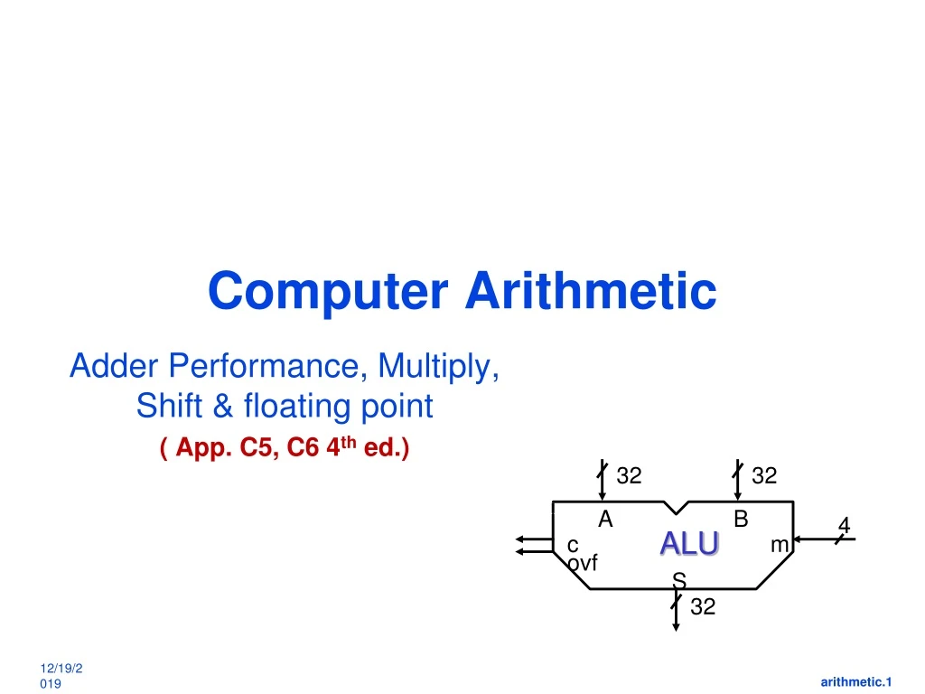
Computer Arithmetic 32 32 A B 4 ALU c m Adder Performance, Multiply, Shift & floating point ( App. C5, C6 4th ed.) ovf S 32
sum Cin A B 1-bit adder Review (Appendix B.5, B.6) Cin a Sum 1unit of delay from Cin to sum b Carry out 2 gate delays Co 2 units of delay from A/B to sum Sum = a!bc! + ab!c! + a!b!c+abc = a b c = XOR Carryout = a!bc + ab!c + abc! + abc
Binvert Operation CarryIn a 0 1 Result b 0 2 1 Less 3 a. CarryOut Binvert Operation CarryIn a 0 1 Result b 0 2 1 Less 3 Set Overflow Overflow detection b. 1-bit ALU: AND, OR, a+b, a+b! ALU Delays Result = 1 gate delay From a to result = 2 Form b to Result = 2 (ignore b invert) Most significant bit
Bnegate a0 Result0 b0 ALU0 Less CarryOut Result1 a1 CarryIn b1 ALU1 0 Less Zero CarryOut Result2 a2 CarryIn b2 ALU2 0 Less CarryOut Result31 a31 CarryIn Set b31 ALU31 Overflow 0 Less Operation Final 32-bit ALU, including zero detect
Behavioral Representation: verilog, RTL FYI) module ALU(A, B, m, S, c, ovf); input [0:31] A, B; input [0:3] m; output [0:31] S; output c, ovf; reg [0:31] S; reg c, ovf; always @(A, B, m) begin case (m) 0: S = A + B; . . . end endmodule • Code written, simulated & verified • translated into hardware (mapped) • How complex digital design is done
Overflow ?? - 4-bit example Decimal Binary Decimal 2’s Complement 0 0000 0 0000 1 0001 -1 1111 2 0010 -2 1110 • Examples: 7 + 3 = 10 but ... • - 4 - 5 = - 9 but ... 3 0011 -3 1101 4 0100 -4 1100 5 0101 -5 1011 6 0110 -6 1010 7 0111 -7 1001 -8 1000 0 1 1 1 1 0 1 1 1 7 1 1 0 0 – 4 3 – 5 + 0 0 1 1 + 1 0 1 1 1 0 1 0 – 6 0 1 1 1 7
Overflow Detection • Overflow: arithmetic result too large (or too small) to represent properly • Example: - 8 4-bit binary number 7 • When adding operands with different signs, overflow cannot occur! • Overflow occurs when adding: • 2 positive numbers and sum is negative • 2 negative numbers and the sum is positive • On your own: Prove you can detect overflow by: • Carry into MSB Carry out of MSB 0 1 1 1 1 0 0 1 1 1 7 1 1 0 0 –4 3 – 5 + 0 0 1 1 + 1 0 1 1 1 0 1 0 – 6 0 1 1 1 7
A0 1-bit ALU Result0 B0 CarryOut0 CarryIn1 A1 1-bit ALU Result1 B1 CarryIn2 CarryOut1 A2 1-bit ALU Result2 B2 CarryIn3 A3 1-bit ALU Result3 B3 Overflow Detection Logic CarryIn0 • Carry into MSB Carry out of MSB • For a N-bit ALU: Overflow = CarryIn[N - 1] XOR CarryOut[N - 1] X Y X XOR Y 0 0 0 0 1 1 1 0 1 1 1 0 Overflow CarryOut3
MIPS ALU requirements • Add, AddU, Sub, SubU, AddI, AddIU • => 2’s complement adder/sub with overflow detection • And, Or, AndI, OrI, Xor, Xori, Nor • => Logical AND, logical OR, XOR, nor • SLTI, SLTIU (set less than) • => 2’s complement adder with inverter, check sign bit of result • ALU must support these ops
CarryIn0 sum Cin A A0 1-bit ALU Result0 B B0 CarryOut0 CarryIn1 A1 1-bit ALU Result1 B1 CarryOut1 CarryIn2 A2 1-bit ALU Result2 B2 CarryOut2 CarryIn3 A3 1-bit ALU Result3 B3 CarryOut3 Ripple Adder Performance? • Critical Path of n-bit Rippled-carry adder is n*CP 1unit of delay from Cin to sum Very slow: Must improve Assume t = carry delay / bit 32- bit ALU needs 32 * t units of delay 64-bit ALU needs 64 * t units of delay 2 units of delay from A/B to sum
Fast Add - Carry Select - review • 4-bit Carry Select Adder • Uses 2 4-bit ripple adder • one adder assumes Cin = 0 • 2nd adder assumes Cin = 1 • Cin selects Sum & Cout
Fast Addition : Carry Lookahead • Carry Inputs can be precomputed by logic c1 = g0 + c0 p0 = a0 b0 + c0 (a0 + b0) p0 = a0 + b0 g0 = a0 b0 c2 = g1 + p1 c1 = g1 + p1 g0 + p1 p0 c0 = a1 b1 + c1 (a1 + b1) p1 = a1 + b1 g1 = a1 b1 c3 = g2 + p2 g1 + p2 p1 g0 + p2 p1 p0 c0 c4 = g3 + p3 g2 + p3 p2 g1 + p3 p2 p1 g0 + p3 p2 p1 p0 c0 C4= func( a3, b3, a2, b2, a1, b1, a0, b0, c0) 1 unit delay each p, g 3 units of delay 1 unit delay 3 units of delay 3 units of delay
S a0 g b0 p S a1 g b1 p S a2 g b2 p S a3 g b3 p Fast Addition: Carry Look Ahead – 4 bits C0 = Cin A B C-out 0 0 0 “kill” 0 1 C-in “propagate” 1 0 C-in “propagate” 1 1 1 “generate” 2 3 c1 = g0 + c0 p0 4 g = a and b 1 delay p = a or b c2 = g1 + g0 p1 + c0 p0 p1 3 4 3 units of delay for c1, c2, c3, (c4) 4 units of delay for S1, S2, S3 3 c3 = g2 + g1 p2 + g0 p1 p2 + c0 p0 p1 p2 4 G0=g3 + p3 g2 + p3 p2 g1 + p3 p2 p1 g0 P0 = p3 p2 p1 p0 3 units of delay for G0 C4 = . . .
Carry Lookahead – 2nd level – 16 bits Add 2nd level abstraction for more practical 4-bit units Each Pi, Gi handles 4 bits at a time, 0-3, 4-7, 8-11,..) P0 = p3 p2 p1 p0 ; G0 = g3 + p3 g2 + p3 p2 g1 + p3 p2 p1 g0 P1 = p7 p6 p5 p4 ; G1 = g7 + p7 g6 + p7 p6 g5 + p7 p6 p5 g4 P2 = p11 p10 p9 p8 ; G2 =g11 + p11 g10 + p11 p10 g9 + p11 p10 p9 g8 P3 = p15 p14 p13 p12; G3 = ……. 3 units of delay for G0, G1, G2, G3 2 units of delay for P0, P1, P2, P3
C L A 4-bit Adder 4-bit Adder 4-bit Adder Fast Addition: Cascaded Carry Look-ahead (16-bit): C0 G0 P0 4 c4 has 4 units of delay c4 = G0 + C0 P0 5 c8 c8 = G1 + G0 P1 + C0 P0 P1 5 units of delay for c8, c12, c16 5 c12 = G2 + G1 P2 + G0 P1 P2 + C0 P0 P1 P2 G c12 P c16 = . . .
Carry Lookahead Homework You are required to calculate the performance of a 16-bit Carry lookahead adder similar to the one discussed in class. The design has 2 options • assuming ripple carry is used inside each 4-bit cell • Carry lookahead is used inside each 4-bit cell • Both cases use carry lookahead at predicting 4-bit boundary carries [c4, c8, c12] • Draw a table showing the delay of each adder bit i.e. Sum0 - Sum 15; as well as the carry at each stage of the design – for the 2 designs
8-bit carry lookahead adder (4-bit block is also CLA) S0 a0 b0 3 S1 a1 b1 2nd level carry lookahead 3 S2 a2 b2 3 G0 P0 S3 a3 b3 6 4 units of delay c4= G0 + c0 P0 5 S4 a4 b4 c5= g4 + c4.p4 Delays 1 4 1 c5 6 S5 a5 b5 c6 = c7 = c6 6 S6 a6 b6 c7 6 S7 G1 P1 a7 b7
a0 b0 a4 b4 Result0 Result4 a1 b1 Result1 Result5 a2 b2 Result6 Result2 2nd level carry lookahead a3 b3 Result3 Result7 c4 a5 b5 a6 b6 a7 b7 8-bit CLA – uses ripple carry inside 4-bit block 0 2 2 3 4 5 6 7 4 5 6 7 8 9 10 11
Additional MIPS ALU requirements • Mult, MultU, Div, DivU => Need 32-bit multiply and divide, signed and unsigned • Sll, Srl, Sra => Need left shift, right shift, right shift arithmetic by 0 to 31 bits
MIPS arithmetic instructions • Instruction Example Meaning Comments • add add $1,$2,$3 $1 = $2 + $3 3 operands; exception possible • subtract sub $1,$2,$3 $1 = $2 – $3 3 operands; exception possible • add immediate addi $1,$2,100 $1 = $2 + 100 + constant; exception possible • add unsigned addu $1,$2,$3 $1 = $2 + $3 3 operands; no exceptions • subtract unsigned subu $1,$2,$3 $1 = $2 – $3 3 operands; no exceptions • add imm. unsign. addiu $1,$2,100 $1 = $2 + 100 + constant; no exceptions • multiply mult $2,$3 Hi, Lo = $2 x $3 64-bit signed product • multiply unsigned multu$2,$3 Hi, Lo = $2 x $3 64-bit unsigned product • divide div $2,$3 Lo = $2 ÷ $3, Lo = quotient, Hi = remainder • Hi = $2 mod $3 • divide unsigned divu $2,$3 Lo = $2 ÷ $3, Unsigned quotient & remainder • Hi = $2 mod $3 • Move from Hi mfhi $1 $1 = Hi Used to get copy of Hi • Move from Lo mflo $1 $1 = Lo Used to get copy of Lo
MULTIPLY (unsigned) • Paper and pencil example : Multiplicand 1000 AMultiplier1001B 1000 a3b0 a2b0 a1b0 a0b0 0000a3b1 a2b1 a1b1 a0b1 0000 a3b2 a2b2 a1b2 a0b2 1000 a3b3 a2b3 a1b3 a0b3Product01001000 • m bits x n bits = m+n bit product • Binary makes it easy: • 0 => place 0 ( 0 x multiplicand) • 1 => place a copy ( 1 x multiplicand) • 2 architectures – Fast Array MPY & Slow Shift & Add
Signed Multiply – 2’s complement Multiplicand 1000 A = -8Multiplier 1001 B = -7 1 10000 1 ~a3b0 a2b0 a1b0 a0b0 1000 ~a3b1 a2b1 a1b1 a0b1 1000 ~a3b2 a2b2 a1b2 a0b2 111111 a3b3 ~a2b3 ~a1b3 ~a0b3 Product00111000 = +56 ~ means bit is complimented 1 extra 1 is added to compensate Complementing & addition of 1, tricks to save complete sign extension every time
0 0 0 0 A3 A2 A1 A0 B0 A3 A2 A1 A0 B1 A3 A2 A1 A0 B2 A3 A2 A1 A0 B3 P7 P6 P5 P4 P3 P2 P1 P0 Fast unsigned Multiply== Array Multiplier Multiplicand A Aj Bi • Can be adapted to accomodate signed MPY • Q: How much hardware for 32 bit multiplier? Critical path? Cell delays ? Product P Multiplier B
A3 A2 A1 A0 A3 A2 A1 A0 A3 A2 A1 A0 A3 A2 A1 A0 Multiplication, using shift & Add Multiplier operation 0 0 0 0 0 0 0 B0 B1 • At each stage shift multiplicand left ( x 2) • Multiplier bit Bi determines : add in shifted multiplicand • Accumulate 2n bit partial product at each stage B2 B3 P7 P6 P5 P4 P3 P2 P1 P0
1000 × 1001 1000 0000 0000 1000 1001000 Multiplication, using shift & Add • long-multiplication approach multiplicand multiplier product Length of product is the sum of operand lengths
Multiplication Hardwareusing shift & Add Initially 0
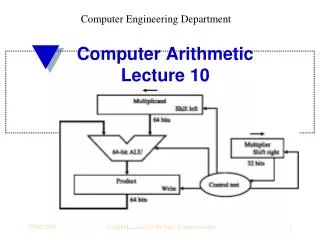
Optimized Multiplierusing shift & Add • Perform steps in parallel: add/shift 32 – bit ALU, multiplicand • One cycle per partial-product addition • ok, if frequency of multiplications is low
1. Test Product0 1a. Add multiplicand to the left half of product & place the result in the left half of Product register Start Multiply Algorithm Product0 = 1 Product0 = 0 Product Multiplicand 2. Shift the Product register right 1 bit. 0000 0011 0010 1: 0010 0011 0010 2: 0001 0001 0010 1: 0011 0001 0010 2: 0001 1000 0010 1: 0001 1000 0010 2: 0000 1100 0010 1: 0000 1100 0010 2: 0000 0110 0010 0000 0110 0010 32nd repetition? No: < 32 repetitions Yes: 32 repetitions Done
MIPS logical instructions • Instruction Example Meaning Comment • and and $1,$2,$3 $1 = $2 & $3 3 reg. operands; Logical AND • or or $1,$2,$3 $1 = $2 | $3 3 reg. operands; Logical OR • xor xor $1,$2,$3 $1 = $2 $3 3 reg. operands; Logical XOR • nor nor $1,$2,$3 $1 = ~($2 |$3) 3 reg. operands; Logical NOR • and immediate andi $1,$2,10 $1 = $2 & 10 Logical AND reg, constant • or immediate ori $1,$2,10 $1 = $2 | 10 Logical OR reg, constant • xor immediate xori $1, $2,10 $1 = ~$2 &~10 Logical XOR reg, constant • shift left logical sll $1,$2,10 $1 = $2 << 10 Shift left by constant • shift right logical srl $1,$2,10 $1 = $2 >> 10 Shift right by constant • shift right arithm. sra $1,$2,10 $1 = $2 >> 10 Shift right (sign extend) • shift left logical sllv $1,$2,$3 $1 = $2 << $3 Shift left by variable • shift right logical srlv $1,$2, $3 $1 = $2 >> $3 Shift right by variable • shift right arithm. srav $1,$2, $3 $1 = $2 >> $3 Shift right arith. by variable
How shift instructions are implemented Two kinds: logical-- value shifted in is always "0" arithmetic-- on right shifts, sign extend shift right logical by 2 "0" msb lsb "0" 1100 1011 shift right arithmetic by 2 msb lsb "0" 1011 1110 instruction can request 0 to 32 bits to be shifted!
Operand 2 Operand 1 BarrelShifter ALU Result ARM :: Barrel Shifter: • Shift value can be either be: • 5 bit unsigned integer • Specified in bottom byte of another register. Example: ADD r0, r1, r2, LSL#7 • Semantics: r2 is shifted left by 7 & then added to r1 2/14
SR3 SR2 SR1 SR0 D3 D2 A6 D1 A5 D0 A4 A3 A2 A1 A0 Barrel Shifter, used in ICs Shift Right using one transistor per switch
Barrel Shifter, used in ICs Shift ……Left & right SL 1 SL 2 SL3 SR2 SR1 SR0 D3 D2 A5 D1 A4 D0 A3 A2 A1 A0
Summary: Multiply & Shift • Multiply: successive refinement to see final design • 32-bit Adder, 64-bit shift register, 32-bit Multiplicand Register • Fast multiply Array multiplier • Shifter: success refinement 1/bit at a time shift register to barrel shifter
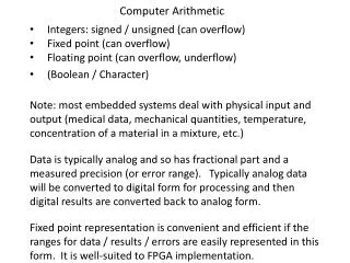
Floating Point Arithmetic • How to represent • numbers with fractions, e.g., 3.1416 • very small numbers, e.g., .000000001 • very large numbers, e.g., 3.15576 109 • Fixed point • Floating point: a number system with floating decimal point • Normalized numbers: no leading 0’s , single digit before decimal point 1.0 x 3.1557 x 35 0.03
Floating Point Notation – IEEE 754 FP exponent decimal point Sign, magnitude 23 -24 6.02 x 10 1.673 x 10 • Issues: • Arithmetic (+, -, *, / ) • Representation, Normal form • Range and Precision, Single, Double • Rounding • Exceptions (e.g., divide by zero, overflow, underflow) radix (base) Mantissa Sign, magnitude e - 127 IEEE F.P. ± 1.M x 2
Floating-Point Arithmetic Floating point numbers in IEEE 754 standard: single precision 1 8 23 S E sign M mantissa: sign + magnitude, normalized binary significand w/ hidden integer bit: 1.M exponent: excess 127 binary integer actual exponent is e = E - 127 0 < E < 255 127 S E-127 N = (-1) 2 (1.M) 0 = 0 00000000 0 . . . 0 -1.5 = 1 01111111 10 . . . 0 Numbers that can be represented is in the range: -126 127 -23 ) 2 (1.0) (2 - 2 to 2 Double Precision IEEE 754 [64-bits] Exponent = 11 bits, Bias = 1023, Mantissa = 52, Sign= 1bit
Exponent Bias used to simplify comparisons • If we use 2’s complement, not good for sorting and comparison0000 0000 1111 1111most negative most positiveexponent exponent
Floating Point – Example review • Represents • bias = 127 for 32-bit word • S = 1: negative 0: positive or zero • Example (from fraction to floating point representation)-0.75
Floating-Point Example - review • Represent –0.75 • –0.75 = (–1)1 × 1.12 × 2–1 • S=1 • Fraction = 1000…002 • Exponent = –1 + Bias = 126 • Single: –1 + 127 = 126 = 011111102 • Double: –1 + 1023 = 1022 = 011111111102 • Single: 1011111101000…00 • Double: 1011111111101000…00
Addition – Multiply Algorithm issues For addition (or subtraction) : (1) compute Ye - Xe (getting ready to align binary point) (2) right shift Xm that many positions to form Xm 2 (3) compute Xm 2 + Ym (4) for multiply, doubly biased exponent must be corrected: Xe = 7 Ye = -3 Excess 8 extra subtraction step of the bias amount Xe-Ye Xe-Ye = 7 + 8 = -3 + 8 4 + 8 + 8 Xe = 1111 Ye = 0101 10100 = 15 = 5 20
Floating Point Addition • Step 1: align, round • Step 2: add • Step 3: normalize, check overflow or underflow • Step 4: round • Example:
Floating Point Multiplication • Step 1: add exponents, subtract bias, Mpy mantissas • Step 2: normalize and check over/underflow • Step 3: round • Step 4: check sign • Example:
FP Adder Hardware • more complex than integer adder • Doing it in one clock cycle - takes too long • Much longer than integer operations • Slower clock would penalize all instructions • FP adder usually takes several cycles • pipelined
FP Adder Hardware Exponents compared Step 1 Smaller number shifted right Step 2 Result iterated until normalized Step 3 Step 4
Floating Point: Overflow & Underflow • Exponent too large to be represented • Underflow: negative exponent too small to fit in exponent field
Summary of Floating Point Arithmetic • IEEE floating point standard 32 bit and 64 bit • Converting decimal numbers to floating point and vice versa • Overflow and underflow • Floating point add and multiply