Download
1 / 43
450 likes | 648 Views
MODIFICATION OF AIR PREHEATERS IN BOILERS OF THERMAL POWER STATION-1 NLC LIMITED,NEYVELI.

E N D
MODIFICATION OF AIR PREHEATERS IN BOILERS OF THERMAL POWER STATION-1 NLC LIMITED,NEYVELI.
PROJECT MEMBERS A.JANARTHANAN (80106114012) S.K.KRISHNAKUMAR (80106114019) N.SARAVANAPRASATH (80106114032) T.SATHISHKUMAR (80106114034) PROJECT GUIDES INTERNAL GUIDE EXTERNAL GUIDE Mr.S.RAJKUMAR Mr.K.GANESAN ASSISTANT PROFESSOR, Chief Manager(FHS) DEPT.OF MECHANICAL ENGINEERING, TPS-I, NLC A.V.C COLLEGE OF ENGINEERING.
FLOW OF THE PRESENTATION TITLE OF THE PROJECT. PROJECT MEMBERS &PROJECT GUIDES. COMPANY PROFILE. OBJECTIVE OF THE PROJECT. REASON FOR CHOOSING THE TOPIC. METHODOLOGY. PROBLEM DEFINITION. LITERATURE REVIEW. SPEPCIFICATIONS. MODEL CALCULATIONS. HEATING ELEMENTS. RESULTS &CONCLUSIONS.
COMPANY PROFILE ABOUT US • Biggest open-cast Mechanised Lignite Mines in India. VISION: • To emerge as a leading mining and power company, continue to be a socially responsible company and strive for Operational excellence in mining and exploration. MISSION: • Strive towards greater cost competitiveness and work towards continued financial strength. • Continually imbibe best practices from the best Indian and International Organisations engaged in Power Generation and Mining. Be a preferred employer by offering attractive avenues of career growth and excellent work environment and by developing human resources to match international standards. • Play an active role in society and be sensitive to emerging environmental issues.
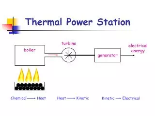
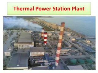
Thermal Power Station I TPS -I is one of the four power stations of a NLC LIMITED its capacity is 600 MW ,12 BOILERS each having a capacity of 220 tonnes/hr, supply steam at 540°C and 90ksc to 6 * 50 Mw turbogenerator and 3 * 100 MW units.
Some of the special features of this TPS-1 are: • First Lignite Power Station in south East Asia . • First pit head power station in India . • First Power Station in India with Soviet Collaboration . • First largest Thermal Power Station in South India. • The power generated from the Thermal Power Station is fed to the grid of Tamil Nadu Electricity Board, the sole beneficiary.
OBJECTIVE OF THE PROJECT • Improving the efficiency of the boiler at TPS-1 • The design value of exit gas temperature in TPS-1 boilers is 160°C. • In our study, we found that the actual exit gas temperature is around 185°C in some boilers. This high gas temperature leads to enormous heat loss through exit gas and ultimately reducing the efficiency of boiler. • Modification of heat recovery system ( i.e.) Air preheaters will utilize temperature of exit flue gas so that there is an improvement in efficiency. • So, we planned to study and analyze the arrangement of air preheaters and suitably modify them so that exit flue gas temperature will be around 160°C which is a designed value
REASON FOR CHOOSING THE TOPIC • The purpose of the air preheater is to recover the heat from the boiler flue gas which increases the thermal efficiency of the boiler by reducing the useful heat lost in the flue gas. • As a consequence, the flue gases are also sent to the flue gas stack (or chimney) at a lower temperature, allowing simplified design of the ducting and the flue gas stack. • It also allows control over the temperature of gases leaving the stack (to meet emissions regulations). • Use highly Efficient Air PreHeaters Save Money, Save Energy!
PROBLEM DEFINITION • Initially a complete study is conducted on the 5th boiler in thermal power station -1 at NLC and we collected data about exit flue gas temperature of the boilers. • These data are collected from electronic display unit automatically and as per the standard procedure. • The exit flue gas temperature coming out of the chimney was found to be around 185°C. • The overall efficiency of boiler was reduced due to the high heat loss in the exit flue gas . • There is also insufficient heat transfer area between the exit flue gas and the air that enters the combustion chamber.
LITERATURE REVIEW • Literature regarding designing of heat exchangers were studied for re designing the existing heat exchanger. • Timo Eirola et al published a paper titled based on “mathematical modeling for a single pass cross flow heat exchangers.” • Basic idea of heat exchanger is to be transfer heat from hot fluid to cold one. • The modeling of heat exchanger needs simultaneous modeling of energy and mass transfer. • For re-designing the existing heat exchanger we are using minimum air required and quantity of flue gas formed. For increasing number of elements the heat transfer per unit area of cast iron preheater is considered.
CONTINUED • Ashish V.Pattekar et al (1999) published a titled “synthesis of optimum controllable heat exchanger “.process integration has paved the way for designs that are optimal from the point of view of energy recovery. • The modern heat exchangers synthesis problem can therefore be stated as the simultaneous optimization of a heat exchanger design from the point of view of energy area and control. • A novel procedure ,genetic algorithms (GA) is used for optimal model of heat exchanger.
MODEL CALCULATIONS: • FORMULA TO FIND THE NUMBER OF HEATING ELEMENT TO BE ADDED: 1) Designed value of heat transfer expected per unit area of cast iron air preheater per kg of flue gas = 1×Cp×dT = 1×0.25× (523-431) = 23 Kcal Where Cp = 0.25kcal/kg.k Dt= t1 –t2 t2 = 158°c t1 = 250°c
2) Actual value of heat transfer expected per unit area of cast iron air preheater per kg of flue gas =1×Cp×dT = 1×0.25× (523-458) = 16.25 k.cal 3) Difference in heat transfer expected per unit area of cast iron air preheater per kg of flue gas =designed value –actual value =23-16.25 = 6.75 k.cal
4) Increase in percentage of heat transfer per unit area of cast iron air preheater = 6.75/23 =29% 5) Heating surface of actual cast iron air preheater=3950sq.m For 29% increase in heat transfer, the increased heating surface of cast iron air preheater is = (29/100) ×3950 =1145.5 ≈ 1146 sq.m
6) Heating surface of re-designed cast iron air preheater =3950+1146 =5096 sq.m 7) Heating surface of one element in cast iron air preheater =4.45sq.m 8) Total number of additional elements to be added to increase the heat transfer area in cast iron airpreheater = Increase in heating surface of CIAPH Heating surface of one element = 1146/4.45 =258 elements . Hence 258 additional elements are to be added in cast iron air preheater to increase its heating surface or heat transfer area.
FORMULAS TO FIND THE OVER ALL INCREASE IN EFFICIENCY OF BOILERS : Steps to be followed: 1) Minimum air required/kg of fuel. 2) Quantity of flue gas formed (mflue) =minimum air required/kg of fuel+29% (Increase in percentage of heat transfer per unit area of cast iron air preheater) 3) Heat absorbed in cast iron air preheater a)Design value: mflue × Cp× ((Temperature of inlet flue gas in °k-(158+273)) b) Actual value: mflue × Cp×((Temperature of inlet flue gas in °k-(185+273)) Where Cp=0.24 kcal/kg.k
4) Percentage of heat loss : = [(design value –actual value)/ design value] This much of percentage area to be increased. 5) To find efficiency improvement Efficiency of boiler =100-various losses in percentage Losses are calculated separately • Efficiency before modification =100-(2.52+%loss in flue gas before modification) ……. (A) • Efficiency after modification =100-(2.52+% losses in flue gas after modification) ……. (B) • Therefore overall increase in efficiency of boiler = (B)-(A) in %.
CALCULATION:( Data from NLC manual, Boiler operation and maintenance) • Minimum air required/kg of fuel. = (100/23) × {(8/3)C+8[H2-(O2/8)]+S} Where C=carbon, H2=hydrogen, O2 =oxygen s=sulphur =11.6C+34.8[H2-(O2/8)]+4.35S • From operation and maintenance manual, [C=31%, H2=2.2%, O2=9%, S=0.3%] =(11.6×0.31)+34.8[0.022-(0.09/8)+(4.35×0.03) =3.596+0.3741+0.1305 =4.1006 kg/kg of fuel.
Therefore minimum air required per kg of fuel =4.1006 kg/kg of fuel. • For 29% excess air to be passed through CIAPH = 4.1006×1.29 =5.28977 kg/kg of fuel • Total gas per hour =61900×5.28977 =327437 kg/hr
Total flue gas generated =61900×5.28977 =327437 kg/hr • Heat absorbed by cast iron air preheater from flue gas (design condition) =327437×0.24×[(245+273)-(158+273)] =327437×0.24×(518-431) = 6836884.7 kcal/hr • Heat absorbed /transformed in CIAPH from flue gas (actual condition) = 327437×0.24× [(245+273)-(185+273)] = 327437×0.24× [(518)-(458)] =4715092.8 kcal/hr
Percentage decrease in heat absorption = (6836884.7- 4715092.8)/ 6836884.7 =0.3103 =31.03% ≈31% • Therefore 31% more heating area is to be added.
Total heating area already available =3950sq.m Therefore 3950×1.31=5174.5sq.m • Each is divided by heating surface of one element in CIAPH given by (5174.5/4.45) =1162.80 ≈1163 tubes. • Therefore 1163 elements are required for new heat transfer area of CIAPH • Additional elements required to increase the total heating area =1163-888(already provided) =275 elements. Hence 275 new elements are to added to increaser the heat transfer area of CIAPH
Various losses in boilers: Assuming the following percentage of losses are constant as referring to NLC, operation and maintenance manual • Losses due to mechanical under burning =1.5% • Losses due to chemical under burning=0.5% • Losses due to radiation effect=0.52% Therefore, Total loss=1.5%+0.5%+0.52% = 2.52%
To find difference in efficiency: 8) Heat lost in flue gas before modification =327437×0.24×185 =14538202kcal • Total heat input =quantity of fuel used ×calorific value of fuel =61900×2450 =151655000kcal.
9) Percentage loss in flue gas before modification, Heat lost in flue gas before modification ×100 = Total heat input = (14538202 /151655000)×100 =9.58% 10) Heat lost in flue gas after modification =327437×0.24×158 =12416411kcal
11) Percentage loss in flue gas after modification Heat lost in flue gas after modification ×100 = Total heat input = (12416411/151655000) ×100 =8.1875%
To find efficiency: Efficiency of boiler =100-losses in percentage a)Efficiency before modification =100-(2.52+9.58) =87.9% b)Efficiency after modification =100-(2.52+8.1875) = 89.29% Therefore overall increase in efficiency of boiler =89.29-87.9 =1.393%
COST ANALYSIS FORMULA TO SOLVE FUEL SAVINGS: 1) Fuel savings=61900×% increase in efficiency =61900×1.393 =86226.7kg of lignite ) In terms of rupees One tonne of lignite =Rs.900 Total fuel savings =86226.7/1000 =86.2267tonnes Total fuel savings in Rs = 86.2267×900 =Rs.77604.03
3) Cost of one heating element =Rs.10000 • Total expense =no. of elements added ×cost of one heating element =275×10000 =Rs.2750000 4) To find payback period Fuel savings in tonnes /hr =61900×1.393 =86226.7 kg of lignite =86.2267 tonnes of lignite
Fuel savings in tonnes /day =86.2267×24 =2069.44 tonnes/day • We know that fuel savings α increase in % of efficiency Fuel savings α 1.393η • Saved fuel consumption per day= (1.393/100)×2069.44 =28.827 tonnes /day
Cost of fuel per tonne=Rs.900 • Total fuel savings/day=28.827×900 =Rs.25944.5 • Total fuel savings/month =25944.5×30 =Rs.778337.07 • Pay back period = (total expense)/( Total fuel savings/day) =2750000/25944.5 =106 days
Total fuel savings per year for one boiler=778337.07×12 =Rs.9340044.8 • Since we are considering about 12 boilers • Therefore fuel savings per year for 12 boilers =9340044.8×12 =Rs.112080537.6 11.2Crores(approx.)
RESULTS • The detailed study of all the 12 boilers was conducted in thermal power station -1 at NLC limited • The exit flue gas temperature of boiler-5 was found to be 185°c as against designed value of 158°c contributing to the loss of boiler efficiency • The efficiency of boiler before the modification of CIAPH is 87.9% • The overall heat transfer coefficient of CIAPH was found to be lower of the order of 14.54W/m²k when compared to other air pre heater • Effectiveness of CIAPH was also lower of the order of 0.40
The redesign of existing CIAPH was proposed. • The additional elements required to increase the heat transfer surface of CIAPH is 275 elements • The efficiency of boiler after the modification of CIAPH is 89.29%. • The overall increases in efficiency of boiler due to redesign of CIAPH is 1.393% • The estimated cost required for the re design 27.50 lakhs. • The pay back period for the proposed design is 106 days • The expected savings per year using the re design was found to Rs.11.2 crores for total of 12 boilers.
CONCLUSION • In this project effectiveness of recovery system was observed, performance analyzed based on careful feasibity analysis, modification of cast iron air preheater was recommended. • The possible improvements in performance was calculated and submitted for consideration. • In addition the following suggestions are put forward for follow up and implementation in order to achieve better efficiency of boiler units.
1. It is strongly recommended to replace the sector of elements to achieve design effectiveness when the defective elements exceed 1% 2. Periodic inspection of heat recovery system is to be carried out to assess insulation fall, ash deposition &general condition of heat transfer area. 3. Energy audit of the boiler is to be carried regularly to trace out the specific area of energy loss.