Download
1 / 32
350 likes | 467 Views
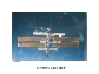
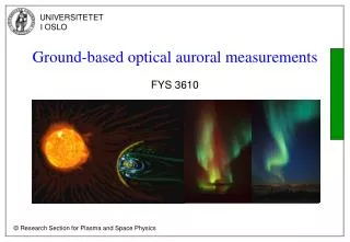
Locations of Auroral Kilometric Radiation Using a 4-station Space-Based Interferometer. Robert Mutel, Ivar Christopher University of Iowa. URSI, Boulder, Jan 2006. Image from ISS. Auroral displays. Altitudes of Aurora. (Red). (Green). Aurora: caused by precipitating keV Electrons.

E N D
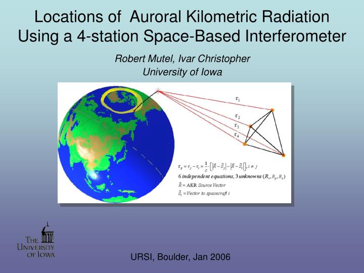
Locations of Auroral Kilometric Radiation Using a 4-station Space-Based Interferometer Robert Mutel, Ivar Christopher University of Iowa URSI, Boulder, Jan 2006
Image from ISS Auroral displays
Altitudes of Aurora (Red) (Green)
Magnetic reconnection: Source of energetic particles for aurora, AKR (?)
Auroral Kilometric RadiationMechanism: Electron Cyclotron Maser Instability
Conditions needed for Cyclotron Maser Instability • Requires fpe/fce << 1 • Requires ∂f/ ∂vperp > 0 e.g. ‘Horseshoe’ velocity distribution • Terrestrial AKR: occurs on B-field lines in acceleration region above auroral zone • AKR also detected from all Jovian planets • May also be responsible for radiation from active stars, AGN Begelman, Ergun, Rees 2005 ApJ
CMI gain, bandwidth CMI Dispersion relation” For γ<<1, expand: Growth rate (imaginary part of ω):
Scientific Question addressed by VLBI location studies of AKR: What is the detailed correspondence between AKR bursts (at 2-4 Re) and auroral features (at 80-300 km)? This addresses the magnetosphere-Ionosphere coupling problem
Requires real-time waveform downlink (4 DSN antennas!) Cluster 4 S/C VLBI array
Cross-correlate waveforms to measure differential delays Note: CCF delay peak width Δτ~ 1/BW Note: When S/C widely separated, only small fraction of AKR bursts are common to all S/C!
Location-finding algorithm 1. In order to determine the AKR source position, the differential delay is measured between the waveform arrival time for each baseline between pairs of spacecraft. For baseline connecting spacecraft i and j, the differential delay is given by 2. The resulting differential delays are further vetted by examining the signed sum of delays on each of the four independent baseline triangles. For an unresolved source, the signed sum of all delays on baseline triangle (i, j, k) must be zero within the delay uncertainty 3. A cubic grid of 512,000 points is examined, delays calculated for each grid point. All points with delays within uncertainty are cobnsidered valid solutions.
VLBI technical details • Snapshot mode! (bursts lasts only ~1s -10s) • Timing uncertainty ±10 μs << 1ms delay uncertainty • Clock: ‘ultra’ stable crystal: δt ~ 10-10 s/s • Real-time downlink (waveforms, 8-bit) • Time: DSN stamped ±1 μs • Essentially no location determination along z (l.o.s.) • 6 baselines: over-determined position solution (3 unknowns: X,Y,Z) • Source unresolved (coherent emission, high Tb) • New VLBI maps every 300ms x 12 freq chan • Frequency channels 12 x 1 KHz • Only delays used – not phases (yet) • S/C positions uncertainty ~1km (3 μs error)
Position Uncertainty If we displace a source in the plane perpendicular to the line of sight by distance xalong the direction of B, the corresponding differential delay will be Assuming x << B << z, we can easily solve for x ~ 500 -1,000 km Assuming x << B << z, a calculation similar to the above, but for a source offset by B/2 in the perpendicular plane results in a position uncertainty ~ 5,000 - 20,000 km
AKR VLBI science results • Association of AKR burst locations with discrete auroral arcs, but: • Some (up to 50%) AKR bursts have no associated auroral features • Some discrete arcs have no AKR emission • Motion of AKR burst centroids (V ~ 100 m/s) • Radiated beamwidth of AKR bursts are much smaller than previously reported (HPBW~ 5°) • Striated AKR triggered by ion stationary structures
Time variations in AKR burst locations 9 Nov 2003 (3 hours) (125, 250, 500 KHz) 29 Dec 2002 (1 ½ hrs)
Correlating Narrowband (Striated) AKR bursts • Problem: Narrow bandwidth implies large uncertainty in delay and location: • Δν ~ 50 Hz → Δτ ~ 20 ms → Δx ~ 4 Re! • Solution: Cross-correlate using longer time window, isolated bursts • Example below: cross–correlation of Synthetic Monochromatic Chirp Signals (τ = 10 ms, Signal + UDP phasor) Δτ ≈ 0.5 ms
Summary • VLBI Technical Summary • 4 S/C VLBI successfully done from space (no ground stations) • Real-time data downlink to DSN (37 kbps) – time stamps added • Software Correlator (IDL) • Onboard crystal Local oscillator, stability: 10-10 s/s (100s) • Uses differential delays from CCF peak (no phase) • Position determination only - no source structure (unresolved) • Position uncertainties ~ ± 200km - 400km at Earth • Narrowband AKR drifting bursts can be mapped using chirp analysis • AKR Science • AKR emission occurs on B field lines associated with discrete auroral arcs • AKR activity center drifts at 80-100 m/s over hours • AKR beam sizes are much smaller than previously assumed (~5°) • Striated AKR triggered by ion stationary structures