Download

1 / 39
390 likes | 852 Views
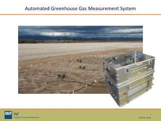
AGMS AUTOMATED GREENHOUSE MONITORING SYSTEM ECE 445: Senior Design Mohd Hafiz Zainudin, Ningci Ho & Muhammad Syauqi Alias Group 32. INTRODUCTION. Benefits. Automatically control environmental conditions within greenhouse allowing any type of plants to be grown all year round

E N D
AGMS AUTOMATED GREENHOUSE MONITORING SYSTEM ECE 445: Senior Design Mohd Hafiz Zainudin, Ningci Ho & Muhammad Syauqi Alias Group 32
Benefits • Automatically control environmental conditions within greenhouse allowing any type of plants to be grown all year round • Eliminates risk of greenhouse not being maintained at specific environmental conditions due to human error • Minimizes labor costs involved in maintaining a greenhouse • Customer able to define specific greenhouse conditions • “Plug-and play” product
Features • Detect and maintain temperatures from -40°C to 125°C • Detect and maintain humidity levels between 5% RH and 95% RH • Detect sunlight and artificial light
Marketability / Business Proposal • Presetting user-defined environmental conditions will allow company to have constant business with consumer • Consumer requires company to recalibrate monitoring system yearly, as well as change preset environmental conditions if necessary • Services can be performed in relatively short period of time, and at reasonably low price, thus not interrupting the monitoring system • In most cases, consumers rarely change environmental conditions in the greenhouse, and therefore prefer the environmental conditions be preset
Build miniature greenhouse which is equipped with automatic monitoring system • Constantly monitor environmental conditions in greenhouse to ensure it remains at preset temperature, light and humidity levels.
Functions • Lower Temperature: 2 Cooling Fans • Raise temperature: Heater (indicated by LED for demonstration purposes) • Decrease humidity level: 2 Exhaust Fans • Increase humidity level: Mister (indicated by LED for demonstration purposes) • Increase lighting condition: Fluorescent Light-bulb
AC Source Relay Light Bulb A to D Converter Photodiode Main Processing Unit Fan A to D Converter Thermistor Heater Mister Humidity Sensor A to D Converter Exhaust Fan Counter Temperature Display System Overview • Voltage output from sensors sent as inputs into PIC • Based on input values, PIC outputs specific voltages to turn ON/OFF devices
Hardware • Environmental Sensors • Microcontroller • Oscillator • Environment Maintaining Devices • Transistors & Relay
Ambient Light Sensor • Manufacturer: Perkin Elmer Optoelectronics VTP-1188-SH • Operating temperature: -20°C to 75°C • Wavelength Measurement Range: 400nm to 1100nm • Current limiting circuit used to control current input into PIC: Voltage Operating Range of PIC: -0.3V to +7.5V Max Current into PIC VDD Pin: 25mA VOUT of Sensor: 0V to 1V Current Limiting: Use 50Ω resistor at output of sensor Max IIN = 1V / 50Ω = 20mA
Temperature Sensor • Manufacturer: Microchip Technology MCP9700A-E/TO • Operating current: 6µA to 12µA • Temperature Measurement Range: -40°C to 125°C • Decoupling circuit to reduce noise from Power Supply: Connect +5V power supply to VDD pin using 200Ω resistor with1µF decoupling capacitor • Current limiting circuit to control current input into sensor: V = IR: 5V / 6µA = 833k Ω 5V / 12µA = 416.7kΩ Therefore use resistor between416.7kΩ and 833kΩ Chose 680kΩ resistor • Allowable input current into PIC so connect directly to PIC: IOUT = 100µA
Humidity Sensor • Manufacturer: TDK Humidity Sensor Unit CHS-UGS • Operating temperature: 5°C to 45°C • Humidity Measurement Range: 5%RH to 95%RH • Current limiting circuit used to control current input into PIC: Voltage Operating Range of PIC: -0.3V to +7.5V Max Current into PIC VDD pin: 25mA VOUT of Sensor: 0V to 1V Current Limiting: Use 50Ω resistor at output of sensor Max IIN = 1V / 50Ω = 20mA
Microcontroller • Manufacturer: Microchip PIC16F877A • Operating Frequency: 20 MHz • Input: Analog/Digital Voltage • Low voltage requirement: +5V • Total Power Dissipation: 1.0W • Voltage Operating Range: VDD = -0.3V to +7.5V • Max Current into VDD pin: 250mA • I/O Voltage Range: -0.3V to VDD + 0.3V • Max Output Current by any I/O pin: 25mA • Ambient temperature under bias: -55 to +125°C • Analog to Digital conversion capability
Oscillator • Manufacturer: Fox Electronics F1100E • Frequency: 20MHz • Voltage: VDD = 5V
Devices • 2 Cooling Fans • Heater (LED) • 2 Exhaust Fans • Mister (LED) • LAMP OFF indicator (LED) • Fluorescent Light-bulb
Transistors to Power Cooling Fans, Exhaust Fans & Relay • Power supply: 5V • Recommended Collector Current: 500mA • Recommended Base Current: 50mA • Transistors used as switches to provide 5V to connected devices. • To ensure circuit functions properly, followed recommended current flow through resistor. • To obtain required current flows, applied Ohm’s law and obtained current limiting resistor for collector to be 10Ω and 100 Ω for the base. • These specifications enable circuit to function properly
Relay to Turn ON/OFF Fluorescent Light-bulb • DC voltage: 5V • DC current: 500mA. • Relay enabled AC current to flow by implementing a switch within the device which is controlled by DC current • The relay supposed to allow AC current through when no dc current is flowing • When DC current is passes through, relay will flick switch to ground, therefore causing open circuit for AC current flow • Applied Ohm’s law to limit current flow and obtained limiting resistor to be 10Ω
Testing of PIC using Function Generator & LEDs • Function generator used to simulate analog inputs of sensors • LEDs used to display appropriate output from PIC • Extreme cases such as voltage greater than or smaller than preset range tested • Preset range of values for light, temperature and humidity tested, and function generator used to calibrate PIC input • Counter tested by checking time duration to output signal after one input is read
Modifying Preset Values for Greenhouse Environmental Conditions • Preset range can be modified by changing values of these variables: 1 ADC point equivalent to 4.883mV. • int16 photoTRIGGER = 635; // <310mV preset value for light switch • int16 minTEMP = 1372; // 670mV preset min sample value for T (30C) • int16 maxTEMP = 1597; // 780mV preset max sample value for T (38C) • int16 minHUMID = 614; // 350mV preset min value for H (30%RH) • int16 maxHUMID = 1065; // 520mV preset max value for H (52%RH)
Testing of Cooling Fans & Exhaust Fans • Power supply: 5V • Max current input: 800mA • Current driven into fan: 500mA • Reason: fan connected to transistor. For transistor, recommended collector current is 500mA. Therefore, use 500mA to power fans • PIC will output 5V, thus use 100Ω resistor in order to limit current as recommended base current to be driven is 50mA. With this connection, fan functioned with sufficient power
Testing of Heater (LED), Mister (LED) & LAMP OFF (LED) • Used LEDs to represent conditions in which heater and mister turned ON • LED also used to signify situation where LAMP is OFF • Voltage supply: 5V • Max current input: 0.1A • Voltage supply for LEDs supplied by output of PIC which will be 0V or 5 V • To supply correct current into LEDs, used current limiting resistors • From the Ohm’s law, V = IR, obtained current limiting resistor for LEDs: • R = V / I = 5V / 0.1A = 50Ω • This specifications allows LEDs to function correctly
Testing of Fluorescent Light-bulb • Voltage supply: 120VAC • To use lamp, had to use a relay • Relay controls current flow from power supply to light bulb • Relay needs 5VDC with 500mA current flow to function as a DC/AC switch. Transistor will be used as a DC/DC switch to allow sufficient power to relay • The switching decision comes from PIC. When PIC outputs digital 0, lamp turns ON. When PIC outputs digital 1, lamp turns OFF • Voltage equivalence of digital output 1 varies from 3.2V to 5V, and digital output 0 varies from 0V to 0.2V. • When relay switch is flicked, 120V AC power for bulb will cut off since switch is thrown to connect with ground. Therefore, bulb turns OFF
Voltage & current inputs into PIC • Voltage input to PIC must be less than 6V • Total current entering PIC must not exceed 300mA • Maximum current entering each pin must not exceed 25mA • Could damage PIC is not compliant
Noise • Thermal sensor did not output values according to data sheet • Due primarily to noise from power supply and surrounding noise • Used decoupling capacitor circuit to minimize noise • Sensor output values as expected
Programming of PIC • First 3 trial codes had issues with timer • Timer problem fixed on fourth trial. Code was still not ready for multitasking (reading all 3 sensors at the same period and output desired signals from appropriate pins) • Greenhouse monitoring system control successfully tested after sixth trial code. This code was implemented for demonstration • Code for seven segment display fully programmed but not fully tested
7-Segment Display • Insufficient time for testing and calibrating • PIC has insufficient ROM when compiling. Attempted to simplify code but determined that second PIC required for this purpose. After several attempts, simplified version of code is completed • Code and logic is functional • 7-segment LED for double digits work as expected • 7-segment LED for single digit does not work as expected. Problem may be caused by Pin C output
Output Current from PIC to Power Devices • Output current from PIC insufficient to turn devices on • Maximum output from one pin is 20mA. Devices such as cooling fans, exhaust fans and relay (used as AC switch) required more current • Problem solved by using transistors
RECOMMENDATIONS • Keep extra sensors in case (damaged humidity sensor – be careful with connections) • Keep extra PIC when programming. Chances of damaging PIC when programming • Modify code line by line and test constantly (will help in debugging process)
SUMMARY • Project successful; features described in Proposal functioned accordingly • Engineering knowledge acquired over the years fully applied and tested • Acquired many new skills and knowledge; improved researching and trouble-shooting techniques • Believe that product will be a success in the market as the “Push for Green” and environmental concerns intensifies in near future
CREDITS THANK YOU: • Professor: Gary Swenson • TA: Tony Mangognia • Parts Shop Personnel • Machine Shop Personnel