Navigation
Navigation. Course T he angle that the ship’s fore and aft line makes with the meridian through the vessel. True Magnetic Compass Heading The direction in which the ship is pointing at any given time. Disturbances: wind, waves, current Track
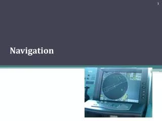

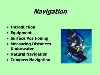
Navigation
E N D
Presentation Transcript
Course • The angle that the ship’s fore and aft line makes with the meridian through the vessel. • True • Magnetic • Compass Heading • The direction in which the ship is pointing at any given time. • Disturbances: wind, waves, current Track • (a) line(s) along which the navigator intends to proceed for a safe passage. • The actual path made over the ground. (If proper correction has been made for the wind, track and course will be identical.) Officers on a passenger ship using charts for navigation Coast guard cadets plotting the course
Important elements (traced on chart and written in voyage plan) are: • planned true course, the distance calculated with ship speed between two points. • “to make good” means to transform the true course and ship speed in corrected values for all changing current conditions or unfavourable sea state. i.e. • to correct values for any drifting influences. Drift angle • The horizontal angle between the axis of a ship and the tangent to its path. Also known as drift correction angle.The calculations determine the course for a vessel to follow in order to get from the point of departure to the destination. • This is a course with respect to ground which can differ from the course to steer if the vessel is deflected sideways by currents and/or winds. The drift angle is also effected by: • Speed of vessel, • Weight of load being carried, • Direction of voyage.
Bearing • The direction in which an object lies from an observer, usually defined by angular measurement between the observer’s meridian and a line from the observer to the object. • True • Relative • Compass • The angle is measured in degrees in a clockwise direction. • The bearings are stated in terms of North, South, East and West. e.g. The bearing to a target may be referenced to true north or to the ship. Bearing referenced to true north is true bearing and bearing referenced to the ship is relative bearing, as above.
A great circle track – orthodrome. • is the circular segment for navigation between the point of departure and point of arrival on the “great circle”. • Greek dromos, “ship way”, on sea surface means that orthodrome is a “corridor” due to having the axis “Great Circle”. • The prefix ortho means “true, correct”. • Circle A-B-A is a Great Circle, “true dromos“, on gnomonic charts. • A straight line drawn on a gnomonic chart would represent a great circle track. When this is transferred to a Mercator chart, it becomes a curve. • The positions are transferred at a convenient interval of longitude and this is plotted on the Mercator chart with the appropriate latitude. • For ships, to navigate on Mercator charts, the orthodroma shall be transformed in “loxodroma”. A Rhumb line or loxodrome • i. e. a line of any line on the Earth’s surface whichcuts all meridians at the same angle, constant bearing. • Loxodrome means “angled drome” - the orthodrometransformed in linear segments (chords) between the point of departure and the point of arrival.
Importance of the maps in Mercator projection • The Mercator projection was originally designed to display accurate compass bearings for sea travel. Any straight line drawn on this projection represents an actual compass bearing. • These true direction lines are rhumb lines (or loxodromes). The route of constant direction between two locations is a always a straight line. For navigation, this is the easiest route to follow, but not necessary the shortest route. • The gnomonic projection is a useful projection for defining routes of navigation for sea, because great circles - the shortest routes between points on a sphere - are shown as straight lines. • Thus, the shortest route between any two locations is always a straight line. No other projection has this special property. In combination with the Mercator map, where all lines of constant direction are shown as straight lines, it assistsnavigators to determine appropriate courses. • Changes in direction for following the shortest route can be determined by plotting the shortest route (great circle or orthodrome) from the Gnomonic map onto the Mercator map. The rhumb lines (lines of constant direction) are shown as straight lines on the Mercator projection. The shortest distance between two points - the great circle path - is shown as a curved line. All great circles - the shortest routes between points on a sphere - are shown as straight lines on the gnomonic projection.
Composite sailing • Method of sailing in which part of the track is a great circle, and part is along a parallel of latitude. • When the great circle would carry a vessel to a higher latitude than desired, a modification of great circle sailing called composite sailing may be used to advantage. • The composite track consists of a great circle from the point of departure and tangent to the limiting parallel, a course line along the parallel, and a great circle tangent to the limiting parallel and through the destination. Solution of composite sailing problems is most easily made with a great circle chart.
Dead reckoning • a method by which the navigator can determine his current position based on an already determined previous position or fix. • the DR helps in predicting sunset, sunrise, rainfall, sighting lights and arrival times. The main usage from DR is that since it helps in future navigation, hazards can be avoided in time. Calculation of a ship's position byconsideration of: • distance logged, • courses steered, and • estimated leeway, • dead reckoning does not take into account the tide, current & wind speed, so is of limited use in most North European waters. Simple dead reckoning (top) with adjustments for leeway (center) and both leeway and current (bottom).
Running fix • Determination of a ship’s position by taking a line of bearing, running a known distance, transferring first line to new position and crossing it with another position line.
Navigation bridge • A view of the navigation bridge during sailing. • The maritime charts and the ship's log book • The wheel and radar • Working space • PC and control panels for various systems onboard the ship.
Aids to navigation RADAR (Radio Detection And Ranging) • It operates by sending out a microwave signal and detecting the microwave beams that bounce off objects (called "targets") and are returned to the receiver. • Radar detects two characteristics of a target: • its relative bearing- its direction relative to your direction of travel; and • its range - the distance from your vessel. • A target may be another ship, land, or any obstruction that causes the radar beam to be reflected back to the ship.
Automatic radar plotting aid (ARPA) The following functions are usually provided: 1. True or relative motion radar presentation. 2. Automatic acquisition of targets plus manual acquisition. 3. Digital read-out of acquired targets which provides course, speed, range, bearing, closest point of approach (CPA), and time to CPA (TCPA). 4. The ability to display collision assessment information directly on the Plan Position Indicator (PPI), using vectors (true or relative) or a graphical Predicted Area of Danger (PAD) display. 5. The ability to perform trial manoeuvres, including course changes, speed changes, and combined course/speed changes. 6. Automatic ground stabilization for navigationpurposes. • ARPA processes radar information much more rapidly than conventional radar but is still subject to the same limitations. • ARPA data is only as accurate as the data that comes from inputs such as the gyro and speed log.
Compass • A gyro compass is anon-magnetic compass which is based on a fast spinning disc and rotation of our planet to automatically find geographical direction. Standard 22 Gyro Compass System • is the most popular gyro compass. • designed as a modular system, the Standard 22 Gyro Compass System is available with various configurations to meet individual requirements. • up to three gyro compasses can be connected to a system. • A magnetic compass consists of a magnetised pointer free to align itself accurately with Earth’s magnetic field. • A compass provides a known reference direction which is of great assistance in navigation. • The cardinal points are north, south, east and west. • A compass can be used in conjunction with a clock and a sextant to provide a very accurate navigation capability.
Aids to navigation • Eco sounder • ship navigationsoftwareRADARpilot720° • Display of electronic charts is standard equipment in inlandnavigation. • RADARpilot720° info provides this basic functionality. • RADARpilot720° info is offered as complete system including PCand software. • It can be upgraded easily for radar overlay, resulting in an approved inland Electronic Chart Display and Information System (ECDIS) navigation system. ECDIS complies with the IMO regulations & can be used as an alternative to paper nautical charts.
Sextants • Navigational or navigation sextants are primarily used for celestial navigation. • A navigational sextant is used to measure the angle of elevation of celestial bodies, usually the sun or moon, so that one's location and direction can be determined. • More generally, a navigational sextant measures the angle between any two objects. • Sextants are instruments that are used for navigating and surveying for maps. • The user looks through an eyepiece, through which they can see the horizon and the reflection from the sky in the mirrors. • If the second mirror on a moving arm is adjusted, the user can make a celestial body, such as a star, the sun or the moon appear to rest on the horizon as they look through the eyepiece. • An angle in degrees can be read off the sextant and used to calculate lunar distance, longitude and where the ship is located on the Earth.
Automatic Identification System (AIS) • AIS information can also be received ashore for the purpose of vessel tracking and management but availability of the information received remains dependent on ships keeping the system switched on. • Although AIS started off as an anti-collision ship-to-ship and ship-to-shore system, it has now taken on many more applications in addition to supplementing existing marine Aids to Navigation (AtoN) systems. • This technology is essentially a business intelligence tool, offering VTS management, vessel tracking, search and rescue and virtual AtoN, etc. Automatic Identification System (AIS)
Bridge simulator A full bridge simulator consists of: • A mock-up of a ship's navigation bridge with telegraph, rudder, tiller, etc. • Bridge instruments, including radar and Electronic Chart Display and Information System (ECDIS.) • Communication equipment. • Simulation of tug assistance. • An immersive visual environment showing the scenery as seen through the bridge windows. • A mathematical model of the forces acting on the ship, to calculate the position, course and speed of the vessel.
Electronic positioning systems • Ships are required to carry a Global Navigation Satellite System (GNSS) receiver or a terrestrial radio-navigation receiver. • While both Omega and Decca have already been discontinued, LORAN C is to be retained for the time being but does not give world-wide coverage. • Within its chain coverage area LORAN provides maritime users with a terrestrial system to back-up GNSS in the event of that system's failure. • The European GALILEO system is still under development. • It is being built by the EuropeanUnion (EU) and EuropeanSpace Agency (ESA). • The fully deployed system will consist of 30 satellites and the associated ground infrastructure. • Galileo will be inter-operable with GPS and Global Navigation Satellite System (GLONASS), operated by the Russian Federation and available to commercial users)), the two other global satellite navigation systems.
We are too reliant on GPS, research warns • Everything from computer synchronisation to ship navigation is being linked to GPS signals, and we may be becoming too reliant on these systems. This is the warning from the Royal Academy of Engineering which has issued a report (March 9, 2011) warning that the system is more vulnerable than we think. • "There is a growing interdependence between systems that people think are backing each other up. And it might well be that if a number these systems fail simultaneously, it will cause commercial damage or just conceivably loss of life. This is wholly avoidable," researcher Dr Martyn Thomas told BBC News. • The report says the weakness of sat-nav signals leaves them open to interference, either from sabotage or from natural phenomena such as solar flares. The signals are equivalent to receiving the light from a bright bulb at a distance of 20,000km. • GPS is becoming very useful at finding our way through unknown city streets, but the worst thing that would happen if we were cut off would be getting a bit lost. But when financial systems and emergency services depend on the same technology, the consequences are more dire. • Said Dr Thomas: "The back-up systems are often inadequate or un-tested; that the jammers are far too easily available and that the risks from them are increasing," adding that "no one has a full picture of the dependencies on GPS and similar systems". The report makes a number of recommendations for actions to take to avoid these problems, but Thomas emphasises the risks could be mitigated if the government and industry co-operated more closely.