CX900e Hardware Components Overview: Power Status & Interface Cards
Explore the CX900e hardware components including power status indicators, front panel interface slots, optional V.24 serial port, and detailed back panel features. Learn about the DEM card, power selection options, and slot configurations for efficient system operation.

CX900e Hardware Components Overview: Power Status & Interface Cards
E N D
Presentation Transcript
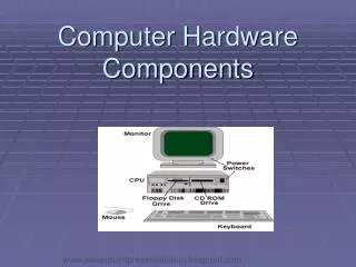
CX900e Hardware Components CX Product Overview Module 3
Power Status light Solid Green = Good Status Flashing Green= Fail Status Push out to Open CX900e Power Status Not used CX900e Front Panel Push out to open
6 interface slots wide variety of interface cards to choose from optional 7th V.24 serial port position + CONSOLE + SLOT5 SLOT 4 SLOT 3 SLOT 2 SLOT 1 SLOT 6 low speed ports max 256 Kbps high speed ports max 2.048 Mbps 7th port V.24 max 128 Kbps CX900e Back Panel
Push out corner fasteners to open cover Foam card holders attached to inside cover Hinged cover I/O Cards Fan Single access Screw Power Selection 115/230V CX900e Chassis Features
Processing Section Slot 1 Slot 2 Slot 3 I/O Section Slot 4 Boot Slot 5 U9 Slot 6 DEM Card Slot 7 7th port Power Section FAN Power Selection Switch 115/230 V CX900e System Board
U32 U34 U33 U9 System Board - Processing Section 8MB DRAM SIMM U47 FLASH expansion (1M, 2M or 4M) U46 Buffers between I/O and Memory 2 MB FLASH application software U29 U30 U28 U31 U23 Boot 128 K FLASH configuration U22 Motorola CPU MC68EN360
SCC 302 CPU SCC SCC System Board - I/O Section Ring Generator Bus Slot 1 MAC SCC Slot 2 SCC 360 CPU SCC Slot 3 SCC Slot 4 Slot 5 DEM Card Slot 6 Slot 7 7th port Ring gen card DEM Card
DEM and Ring Generator Card ribbon cable connection to back panel V.24Interface DB-25 Connector 7th port Max speed 128 Kbps Black Magic 302 CPU 7th port jumpers DTE/DCE Ring generator card MountingBracket
1. What is the difference between a CX900 and CX900e? 2. How many slots can operate at 2.048 Mbps? 3. What is the purpose of the DEM card? 4. What power options are available? 5. In which case should the ring generator be installed? CX900e Review Questions