Download
1 / 61
650 likes | 1.19k Views
Analog to Digital Converters. Stu Godlasky Nikita Pak James Potter. Introduction. What is an analog to digital converter (ADC) Going from analog to digital Types and properties of ADC. What is an Analog to Digital Converter. Converts an analog signal to discrete time digital

E N D
Analog to Digital Converters Stu Godlasky Nikita Pak James Potter
Introduction • What is an analog to digital converter (ADC) • Going from analog to digital • Types and properties of ADC
What is an Analog to Digital Converter • Converts an analog signal to discrete time digital • Computers need digital. (On / Off , High / Low , 1/0)
Going from Analog to Digital • Two step process • Sampling – Measuring analog signal at uniform time intervals • Quantization – Assigning discrete measurements a binary code (each sample will have a binary number associated with it) Example of digital signal from 3 bit ADC 010 010 011 T1 T2 T3 T4
Aliasing • Every analog signal has a frequency • Nyquist Frequency (half sampling frequency) • Aliasing occurs when signal above Nyquist frequency
Quantization Error • Analog (infinite values) – Digital (finite values) • Upon reconstruction of analog signal • Increases as resolution decreases Resolution - Q EFSR - full scale voltage range N = Number of discrete voltage intervals N = 2k where k is the number of bits
Quantization Error • Quantized signal only has values at midpoint of voltage band
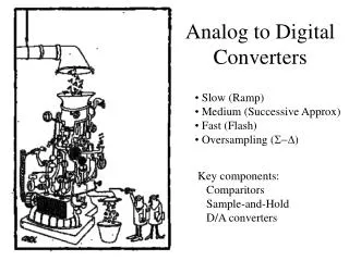
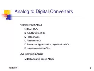
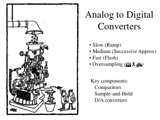
Types of Analog to Digital Converters • Dual Slope A/D Converter • Successive Approximation A/D Converter • Flash A/D Converter • Delta – Sigma A/D Converter
Dual Slope Analog to Digital Converter • Also referred to as an Integrating ADC Integrator
Dual Slope Analog to Digital Converter • Converts in two phases (ramp up / ramp down ) • Input voltage measurement not dependant on integrator components
Dual Slope Analog to Digital Converter Pros • Conversion result is insensitive to errors in the component values • Fewer adverse affects from noise • High accuracy • Cons • Slow • Accuracy is dependant on the use of precision external components • Cost
Successive Approximation Analog To Digital Converter • DAC = Digital to Analog Converter • EOC = End of Conversion • SAR = Successive Approximation Register • S/H = Sample and Hold Circuit • Vin = Input Voltage • Vref = Reference Voltage
Successive Approximation Analog to Digital Converter • Uses an n-bit DAC and original analog results • Performs a bit by bit comparison of VDAC and Vin • If Vin > VREF / 2 MSB set to 1 otherwise 0 • If Vin > VDAC Successive Bits set to 1 otherwise 0
Successive Approximation ADC Example • 10 bit ADC • Vin = 0.6 V • Vref = 1V N = 2n (n = number of bits) N = 210 = 1024 Vref = 1V/ 1024 = 0.0009765625V (resolution)
Successive Approximation Digital to Analog Converter Pros • Capable of high speed and reliable • Medium accuracy compared to other ADC types • Good tradeoff between speed and cost • Capable of outputting the binary number in serial (one bit at a time) format. • Cons • Higher resolution successive approximation ADCs will be slower
Flash Analog to Digital Converter • Also called a parallel ADC • 2N – 1 Comparators • 2N Resistors • Control Logic (encoder)
Flash Analog to Digital Converter • Uses the resistors to divide reference voltage into intervals • Uses comparators to compare Vin and the reference voltages • Encoder takes the output of comparators and uses control logic to generate binary digital output
Flash Analog to Digital Converter Pros • Very Fast (Fastest) • Very simple operational theory • Speed is only limited by gate and comparator propagation delay • Cons • Expensive • Prone to produce glitches in the output • Each additional bit of resolution requires twice the comparators and resistors
Sigma-Delta Analog to Digital Converter • Input over sampled, goes to integrator • Integration compared with ground • Iteration drives integration of error to zero • Output is a stream of serial bits
Sigma-Delta Analog to Digital Converter Pros • High resolution • No need for precision components • Cons • Slow due to over sampling • Only good for low bandwidth
Analog to Digital Converter Applications Nikita Pak
Analog to Digital Converter Applications • Music recording • Data acquisition/measurement devices • thermocouples • digital multimeters • strain gauges • Consumer Products • cell phones • digital cameras
Music Recording • A to D used to convert sound pressure waves into discrete digital signal (later, D to A used to convert back to an electrical signal for a speaker) • Saves a tremendous amount of space • Ex. CD samples at 44.1 kHz (Nyquistfrequency = 22.05 kHz is higher than human ear can detect) • CD recording often done with flash A to D
Data Acquisition • Data acquisition: the process of obtaining signals from sensors that measure physical conditions • Sensors give analog voltage that must be converted to work on a computer • Most National Instruments DAQ’s use successive approximation A to D
Measurement Devices • Thermocouple: a junction of dissimilar metals creates a voltage difference that is temperature dependent • Digital multimeter: converts signal to a voltage and amplifies it for measurement • More accurate than analog counterparts
Measurement Devices • Strain gauge: most common type measures the change in resistance as a metal pattern is deformed
Consumer Products • Cell phones: convert your voice into a digital signal so it can be more efficiently transmitted by compressing the signal • Digital camera ccd: absorbed photons create charges that are converted into a sequence of voltages • These voltages are converted to a digital signal • Both often use flash A to D
ADC on Your Microcontroller Input Pins ADC Built-into MC9S12C32
ADC in Block Diagram ATD 10B8C Port AD
Details of ATD 10B8C • Analog-To-Digital • Resolution: 8 or 10 Bits (manually chosen) • 8-Channel multiplexed inputs • Conversion time: 7 µs (for 10 bit mode) • Optional external trigger • “Successive approximation” type ADC
ATD 10B8C Block Diagram Results of Successive Approximation Reference Voltages Source V source “Holds” Source Voltage
RegistersandSetting Up Your ATD10B8C James Potter
ADC Registers • All information about registers found in Chapter 8 of MC9S12C Family Reference Manual • 8 Result Registers • 6 Control Registers • 2 Status Registers • 2 Test Registers • 1 Digital Input Enable Register • 1 Digital Port Data Register
Result Registers 8 registers, Each with High and low byte
Result Registers:Left-Justified (Default) • High Byte • Low Byte
Result Registers:Right-Justified • High Byte • Low Byte
Single Channel (MULT = 0)Single Conversion (SCAN = 0) ATDDR7 ATDDR6 7 6 5 4 3 2 1 0 ATDDR5 ATDDR4 ATDDR3 Port AD Result Register Interface ATDDR2 ATDDR1 ATD Converter ATDDR0